8. Chapter RGB LED
Earlier, we have learned to apply the analog port and ADC of the control board. Now, we’ll use ADC to control RGB LED.
8.1. Project Control RGB LED through Potentiometer
RGB LED has three different-color LEDs inside, and we will use 3 potentiometers to control these 3 LEDs to emit light with different brightness, and observe what will happen.
8.1.1. Component List
Control board x1 |
Breadboard x1 |
||
USB cable x1 |
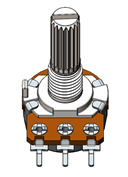
Rotary potentiometer x3 |
RGB LED x1 |
Resistor 220Ω x3 |
Jumper M/M x2 |
|||


8.1.2. Component Knowledge
8.1.2.1. RGB LED
A RGB LED has 3 LEDs integrated into one LED component. It can respectively emit Red, Green and Blue light. In order to do this, it requires 4 pins (this is also how you identify it). The long pin (1) is the common which is the Cathode (+) or positive lead, the other 3 are the Anodes (-) or negative leads. A rendering of a RGB LED and its electronic symbol are shown below. We can make RGB LED emit various colors of light and brightness by controlling the 3 Anodes (2, 3 & 4) of the RGB LED
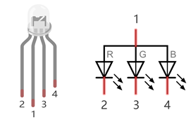
Red, Green, and Blue light are called 3 Primary Colors when discussing light (Note: for pigments such as paints, the 3 Primary Colors are Red, Blue and Yellow). When you combine these three Primary Colors of light with varied brightness, they can produce almost any color of visible light. Computer screens, single pixels of cell phone screens, neon lamps, etc. can all produce millions of colors due to phenomenon.
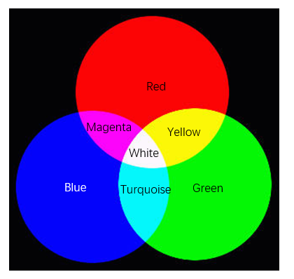
We know from the previous section that, control board controls LED to emit a total of 256(0-255) different brightness via PWM. So, through different combinations of RGB light brightness, we can create 256^3=16777216(16Million) colors.
8.1.3. Circuit
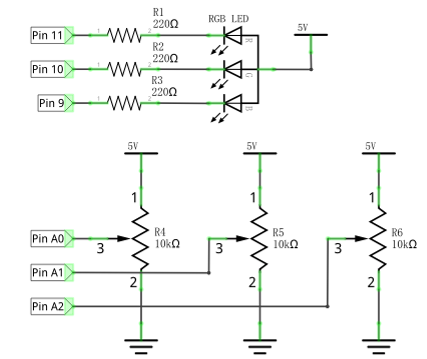
Use pin A0, A1, A2 ports of the control board to detect the voltage of rotary potentiometer, and control RGB LED by pin 9, 10, 11.
Schematic diagram |
|
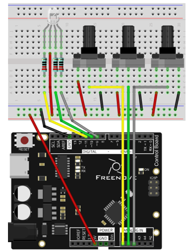
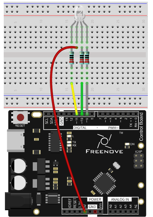
Hardware connection |
|
8.1.4. Sketch
8.1.4.1. Sketch 8.1.1
Now, write code to detect the voltages of these three rotary potentiometers, and convert them into PWM duty cycle to control 3 LEDs inside the RGB LED.
 1/*
 2  Sketch 8.1.1
 3  Control RGB LED through Potentiometer
 4
 5  modified 2016/5/13
 6  by http://www.freenove.com
 7*/
 8
 9// set pin numbers:
10int ledPinR = 11;   // the number of the LED R pin
11int ledPinG = 10;   // the number of the LED G pin
12int ledPinB = 9;    // the number of the LED B pin
13
14void setup() {
15  // initialize the LED pin as an output:
16  pinMode(ledPinR, OUTPUT);
17  pinMode(ledPinG, OUTPUT);
18  pinMode(ledPinB, OUTPUT);
19}
20
21void loop() {
22  int adcValue;     // Define a variable to save the ADC value
23  // Convert analog of A0 port into digital, and work as PWM duty cycle of ledPinR port
24  adcValue = analogRead(A0);
25  analogWrite(ledPinR, map(adcValue, 0, 1023, 0, 255));
26  // Convert analog of A1 port into digital, and work as PWM duty cycle of ledPinG port
27  adcValue = analogRead(A1);
28  analogWrite(ledPinG, map(adcValue, 0, 1023, 0, 255));
29  // Convert analog of A2 port into digital, and work as PWM duty cycle of ledPinB port
30  adcValue = analogRead(A2);
31  analogWrite(ledPinB, map(adcValue, 0, 1023, 0, 255));
32}
33
In the code, we get the voltages of three rotary potentiometers, and convert them into PWM duty cycle to control the three LEDs of the RGB LED to emit light with different brightness.
Verify and upload the code, rotate the three rotary potentiometer shaft, and you can see the LED light change in its color and brightness.
8.2. Project Multicolored LED
In the previous section, we have finished controlling the RGB LED to emit light with different color and brightness through three potentiometers. Now, we will try to make RGB LED emit multicolored lights automatically.
8.2.1. Component List
Control board x1 |
Breadboard x1 |
|
USB cable x1 |
RGB LED x1 |
Resistor 220Ω x10 |
Jumper M/M x11 |
||
8.2.2. Circuit
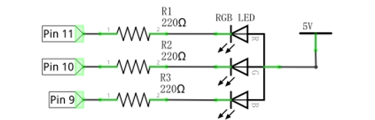
Use pin 9, 10, 11 of the control board to control RGB LED.
Schematic diagram |
|
Hardware connection |
|
8.2.3. Sketch
8.2.3.1. Sketch 8.2.1
Now, write code to generate three random numbers, and convert them into PWM duty cycle to control the three LEDs of RGB LED.
 1/*
 2  Sketch 8.2.1
 3  Colorful LED
 4
 5  modified 2016/5/13
 6  by http://www.freenove.com
 7*/
 8
 9// set pin numbers:
10int ledPinR = 11;   // the number of the LED R pin
11int ledPinG = 10;   // the number of the LED G pin
12int ledPinB = 9;    // the number of the LED B pin
13
14void setup() {
15  // initialize the LED pin as an output:
16  pinMode(ledPinR, OUTPUT);
17  pinMode(ledPinG, OUTPUT);
18  pinMode(ledPinB, OUTPUT);
19}
20
21void loop() {
22  // Generate three random numbers between 0-255 as the output PWM duty cycle of ledPin
23  rgbLedDisplay(random(256), random(256), random(256));
24  delay(500);
25}
26
27void rgbLedDisplay(int red, int green, int blue) {
28  // Set three ledPin to output the PWM duty cycle
29  analogWrite(ledPinR, constrain(red, 0, 255));
30  analogWrite(ledPinG, constrain(green, 0, 255));
31  analogWrite(ledPinB, constrain(blue, 0, 255));
32}
33
In the code, we create three random numbers, and convert them into PWM duty cycle to control the three LEDs of RGB LED to emit light with different brightness. At regular intervals, a new random number will be created, so RGB LED will start flashing light with different colors and brightness.
- random(min, max)
random (min, max) function is used to generate random number, and it will return a random value in the range (min, Max-1).
You can also use random (max) function, the function set the minimum value into 0 by default, and returns a random value in the range (0, Max-1).
Verify and upload the code, and RGB LED starts flashing with different colors and brightness.