5. Chapter RGB LED
In this chapter, we will learn how to control a RGB LED.
An RGB LED has 3 LEDs integrated into one LED component. It can respectively emit Red, Green and Blue light. In order to do this, it requires 4 pins (this is also how you identify it). The long pin (1) is the common which is the Anode (+) or positive lead, the other 3 are the Cathodes (-) or negative leads. A rendering of a RGB LED and its electronic symbol are shown below. We can make RGB LED emit various colors of light and brightness by controlling the 3 Cathodes (2, 3 & 4) of the RGB LED
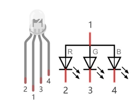
Red, Green, and Blue light are called 3 Primary Colors when discussing light (Note: for pigments such as paints, the 3 Primary Colors are Red, Blue and Yellow). When you combine these three Primary Colors of light with varied brightness, they can produce almost any color of visible light. Computer screens, single pixels of cell phone screens, neon lamps, etc. can all produce millions of colors due to phenomenon.

RGB
If we use a three 8 bit PWM to control the RGB LED, in theory, we can create 28*28*28=16777216 (16 million) colors through different combinations of RGB light brightness.
Next, we will use RGB LED to make a multicolored LED.
5.1. Project Multicolored LED
5.1.1. Component List
Raspberry Pi (with 40 GPIO) x1 GPIO Extension Board & Ribbon Cable x1 Breadboard x1 |
RGB LED x1
|
|
Resistor 220Ω x3
|


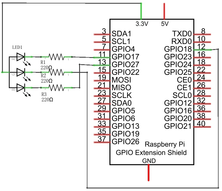
5.1.2. Circuit
Schematic diagram
|
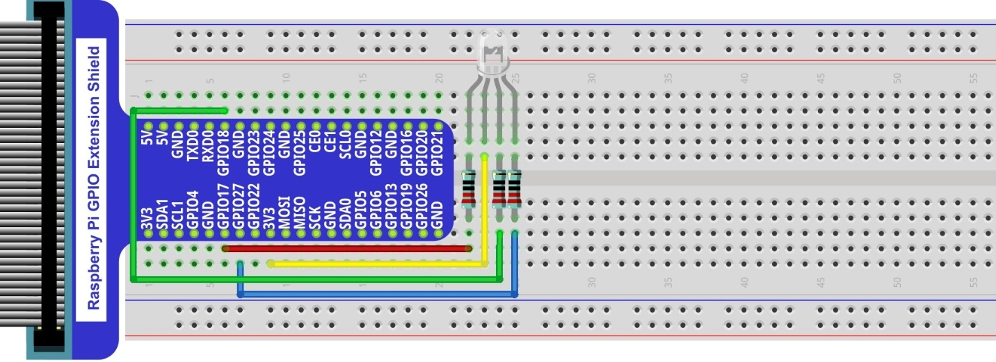
Hardware connection. If you need any support,please feel free to contact us via:
|
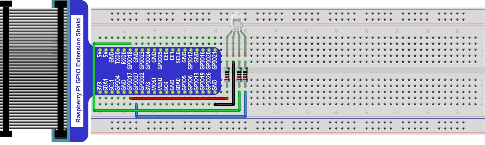
Note
In this kit, the RGB led is Common anode. The voltage difference between LED will make it work. There is no visible GND. The GPIO ports can also receive current while in output mode.If circuit above doesn’t work, the RGB LED may be common cathode. Please try following wiring.There is no need to modify code for random color.
5.1.3. Code
We need to use the software to make the ordinary GPIO output PWM, since this project requires 3 PWM and in RPi only one GPIO has the hardware capability to output PWM,
5.1.3.1. C Code Colorful LED
First, observe the project result, and then learn about the code in detail.
Hint
If you have any concerns, please contact us via: support@freenove.com
Use
cdcommand to enter 05.1.1_ColorfulLED directory of C code.
$ cd ~/Freenove_Kit/Code/C_Code/05.1.1_ColorfulLED
Use following command to compile
ColorfulLED.cand generate executable fileColorfulLED.
Note
In this project, the software PWM uses a multi-threading mechanism. So -lpthread option need to be add to the compiler.
$ gcc ColorfulLED.c -o ColorfulLED -lwiringPi -lpthread
And then run the generated file
ColorfulLED.
$ sudo ./ColorfulLED
After the program is executed, you will see that the RGB LED shows lights of different colors randomly.
The following is the program code:
 1/**********************************************************************
 2* Filename    : ColorfulLED.c
 3* Description : Random color change ColorfulLED
 4* Author      : www.freenove.com
 5* modification: 2019/12/27
 6**********************************************************************/
 7#include <wiringPi.h>
 8#include <softPwm.h>
 9#include <stdio.h>
10#include <stdlib.h>
11
12#define ledPinRed    0
13#define ledPinGreen  1
14#define ledPinBlue   2
15
16void setupLedPin(void)
17{
18	softPwmCreate(ledPinRed,  0, 100);	//Creat SoftPWM pin for red
19	softPwmCreate(ledPinGreen,0, 100);  //Creat SoftPWM pin for green
20	softPwmCreate(ledPinBlue, 0, 100);  //Creat SoftPWM pin for blue
21}
22
23void setLedColor(int r, int g, int b)
24{
25	softPwmWrite(ledPinRed,   r);	//Set the duty cycle
26	softPwmWrite(ledPinGreen, g);   //Set the duty cycle
27	softPwmWrite(ledPinBlue,  b);   //Set the duty cycle
28}
29
30int main(void)
31{
32	int r,g,b;
33
34	printf("Program is starting ...\n");
35
36	wiringPiSetup();	//Initialize wiringPi.
37
38	setupLedPin();
39	while(1){
40		r=random()%100;  //get a random in (0,100)
41		g=random()%100;  //get a random in (0,100)
42		b=random()%100;  //get a random in (0,100)
43		setLedColor(r,g,b);//set random as the duty cycle value
44		printf("r=%d,  g=%d,  b=%d \n",r,g,b);
45		delay(1000);
46	}
47	return 0;
48}
First, in subfunction of ledInit(), create the software PWM control pins used to control the R, G, B pin respectively.
1void setupLedPin(void)
2{
3	softPwmCreate(ledPinRed,  0, 100);	//Creat SoftPWM pin for red
4	softPwmCreate(ledPinGreen,0, 100);  //Creat SoftPWM pin for green
5	softPwmCreate(ledPinBlue, 0, 100);  //Creat SoftPWM pin for blue
6}
Then create subfunction, and set the PWM of three pins.
1void setLedColor(int r, int g, int b)
2{
3	softPwmWrite(ledPinRed,   r);	//Set the duty cycle
4	softPwmWrite(ledPinGreen, g);   //Set the duty cycle
5	softPwmWrite(ledPinBlue,  b);   //Set the duty cycle
6}
Finally, in the “while” loop of main function, get three random numbers and specify them as the PWM duty cycle, which will be assigned to the corresponding pins. So RGB LED can switch the color randomly all the time.
1while(1){
2	r=random()%100;  //get a random in (0,100)
3	g=random()%100;  //get a random in (0,100)
4	b=random()%100;  //get a random in (0,100)
5	setLedColor(r,g,b);//set random as the duty cycle value
6	printf("r=%d,  g=%d,  b=%d \n",r,g,b);
7	delay(1000);
8}
The related function of PWM Software can be described as follows:
-
long random();
This function will return a random number.
Hint
For more details about Software PWM, please refer to: https://github.com/WiringPi/WiringPi