Project Potentiometer & Motor
In this project, a rotary potentiometer is used to control a motor.
Component list
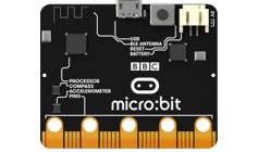
Microbit x1
|
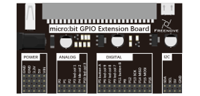
Expansion board x1
|
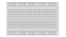
Breakboard x1
|
USB cable x1
|
F/M x9 M/M x3 |
Motor x1
|
Rotary potentionmeter x1
|
L293D x1
|

Component knowledge
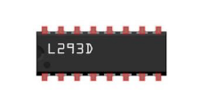
L293D
L293D is an IC Chip (Integrated Circuit Chip) with a 4-channel motor drive. You can drive a Unidirectional DC Motor with 4 ports or a Bi-Directional DC Motor with 2 ports or a Stepper Motor (Stepper Motors are covered later in this Tutorial).
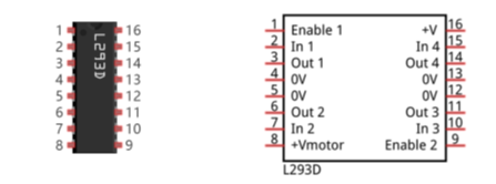
Port description of L293D module is as follows:
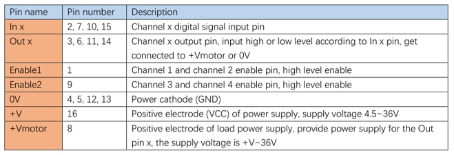
For more details, please see datasheet.
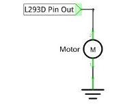
When using the L293D to drive a DC Motor, there are usually two connection options.
The following connection option uses one channel of the L239D, which can control motor speed through the PWM, However the motor then can only rotate in one direction.
The following connection uses two channels of the L239D: one channel outputs the PWM wave, and the other channel connects to GND. Therefore, you can control the speed of the motor. When these two channel signals are exchanged, not only controls the speed of motor, but also can control the speed of the motor.
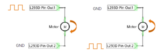
In practical use the motor is usually connected to channel 1 and by outputting different levels to in1 and in2 to control the rotational direction of the motor, and output to the PWM wave to Enable1 port to control the motor’s rotational speed. If the motor is connected to channel 3 and 4 by outputting different levels to in3 and in4 to control the motor’s rotation direction, and output to the PWM wave to Enable2 pin to control the motor’s rotational speed.
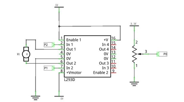
Circuit
Schematic diagram |
|
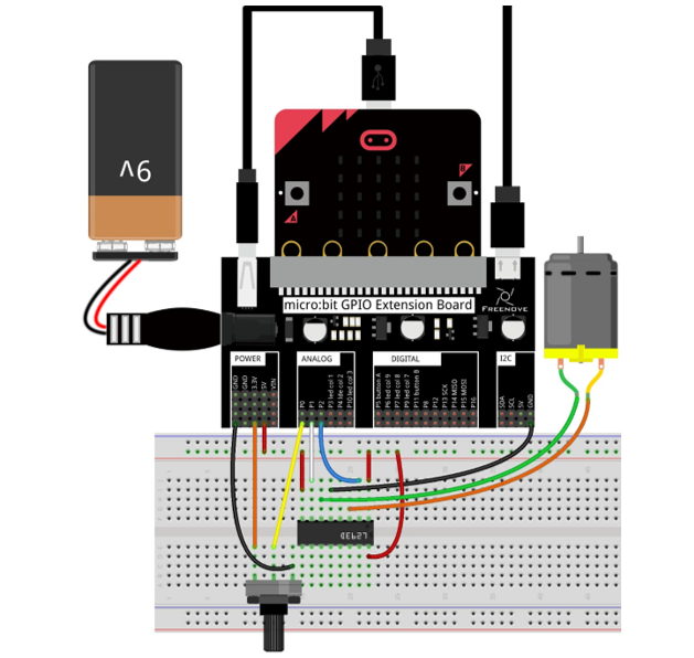
Hardware connection |
|
Block code
Open MakeCode first. Import the .hex file. The path is as below:
File type |
Path |
File name |
HEX file |
../Projects/BlockCode/21.1_Motor |
Motor.hex |
After importing successfully, the code is shown as below:
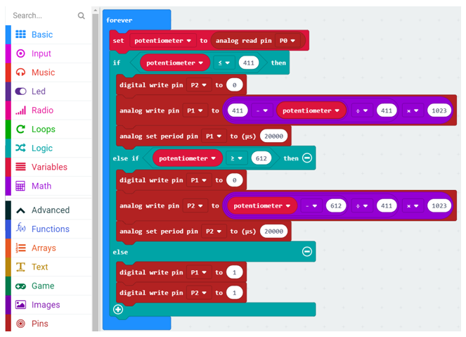
Check the connection of the circuit and verify it correct. Download the code into the micro:bit and rotate the potentiometer. When the potentiometer is in the middle position, the motor stops rotating. When the potentiometer gets away from middle position, the motor speed increases. The potentiometer moves to the limit and the motor speed reaches its maximum value. When the potentiometer is on a different side, the rotating direction of motor is different.
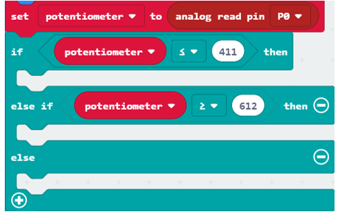
Read the analog value of the P0 pin of the potentiometer. When the analog value is less than 411, the motor rotates forward. When the analog value is greater than 612, the motor reverses. When the analog value is between 411 and 612, the motor does not rotate.
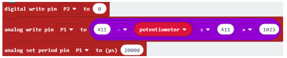
Set P2 to low level. P1 outputs PWM signal with an interval of 20ms and duty cycle changes with the change of potentiometer variable, then motor rotates forward.
Set P1 to low level, P2 output PWM signal with an interval of 20ms, duty cycle changes with the change of potentiometer variable, then motor rotates in a reverse direction.
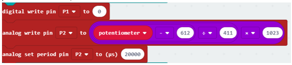
When P1, P2 pin output high level, motor does not rotate.

Reference
Block |
Function |
|
Write an analog signal (0 through 1023) to the pin you set. |
|
Configure the period of Pulse Width Modulation (PWM) on the specified analog pin. Before you call this function, you should set the specified pin as analog. |


Python code
Open the .py file with Mu. Code, the path is as below:
File type |
Path |
File name |
Python file |
../Projects/PythonCode/21.1_Motor |
Motor.py |
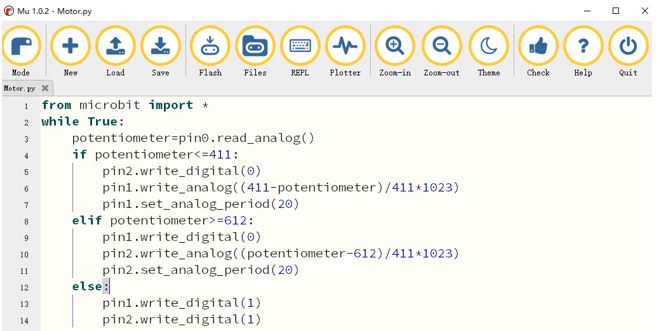
After loading successfully, the code is shown as below:
Check the connection of the circuit and verify it correct. Download the code into the micro:bit and rotate the potentiometer. When the potentiometer is in the middle position, the motor stops rotating. When the potentiometer gets away from middle position, the motor speed increases. The potentiometer moves to the limit and the motor speed reaches its maximum value. When the potentiometer is on a different side, the rotating direction of motor is different.
The following is the program code:
 1from microbit import *
 2while True:
 3    potentiometer=pin0.read_analog()
 4    if potentiometer<=411:
 5        pin2.write_digital(0)
 6        pin1.write_analog((411-potentiometer)/411*1023)
 7        pin1.set_analog_period(20)
 8    elif potentiometer>=612:
 9        pin1.write_digital(0)
10        pin2.write_analog((potentiometer-612)/411*1023)
11        pin2.set_analog_period(20)
12    else:
13        pin1.write_digital(1)
14        pin2.write_digital(1)
Read the analog value of the P0 pin of the potentiometer. When the analog value is less than 411, the motor rotates forward. When the analog value is greater than 612, the motor reverses. When the analog value is between 411 and 612, the motor does not rotate.
potentiometer=pin0.read_analog()
if potentiometer<=411:

elif potentiometer>=612:

else:
Set P2 to low level. P1 outputs PWM signal with an interval of 20ms, duty cycle changes with potentiometer variable, then motor rotates forward.
1pin2.write_digital(0)
2pin1.write_analog((411-potentiometer)/411*1023)
3pin1.set_analog_period(20)
Set P1 to low level. P2 outputs PWM signal with an interval of 20ms, duty cycle changes with the change of potentiometer variable, then motor rotates in a reverse direction.
1pin1.write_digital(0)
2pin2.write_analog((potentiometer-612)/411*1023)
3pin2.set_analog_period(20)
When P1, P2 pins output high level, motor does not rotate.
1pin1.write_digital(1)
2pin2.write_digital(1)
Reference
- pin.set_analog_period(int)
sets the interval; of the PWM output of the pin in milliseconds
- pin.write_analog(value)
value is between 0 and 1023