Chapter 15 74HC595 & 7-Segment Display
In this chapter, we will introduce the 7-Segment Display.
Project 15.1 7-Segment Display.
We will use 74HC595 to control 7-segment display and make it display hexadecimal character “0-F”.
Component List
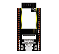
ESP32-WROVER x1
|
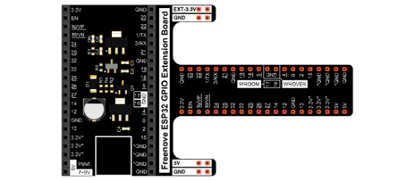
GPIO Extension Board x1
|
||
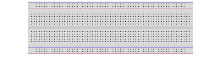
Breadboard x1
|
|||
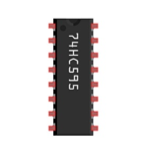
74HC595
|
Resistor 220Ω x8
|
Jumper M/M
|
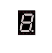
7-segment display x1
|
Component knowledge
7-segment display
A 7-segment display is a digital electronic display device. There is a figure “8” and a decimal point represented, which consists of 8 LEDs. The LEDs have a common anode and individual cathodes. Its internal structure and pin designation diagram is shown below:
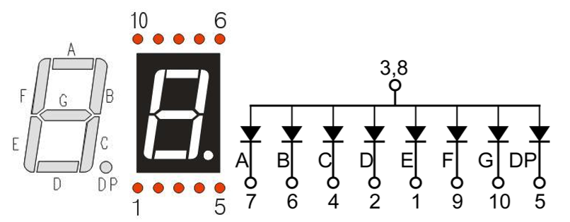
As we can see in the above circuit diagram, we can control the state of each LED separately. Also, by combining LEDs with different states of ON and OFF, we can display different characters (Numbers and Letters). For example, to display a “0”: we need to turn ON LED segments A, B, C, D, E and F, and turn OFF LED segments G and DP.
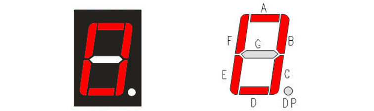
In this project, we will use a 7-Segment Display with a common anode. Therefore, when there is an input low level to a LED segment the LED will turn ON. Defining segment “A” as the lowest level and segment “DP” as the highest level, from high to low would look like this: “DP”, “G”, “F”, “E”, “D”, “C”, “B”, “A”. Character “0” corresponds to the code: 1100 0000b=0xc0.
For detailed code values, please refer to the following table (common anode).
CHAR |
DP |
G |
F |
E |
D |
C |
B |
A |
Hex |
ASCII |
|---|---|---|---|---|---|---|---|---|---|---|
0 |
1 |
1 |
0 |
0 |
0 |
0 |
0 |
0 |
0xc0 |
1100 0000 |
1 |
1 |
1 |
1 |
1 |
1 |
0 |
0 |
1 |
0xf9 |
1111 1001 |
2 |
1 |
0 |
1 |
0 |
0 |
1 |
0 |
0 |
0xa4 |
1010 0100 |
3 |
1 |
0 |
1 |
1 |
0 |
0 |
0 |
0 |
0xb0 |
1011 0000 |
4 |
1 |
0 |
0 |
1 |
1 |
0 |
0 |
1 |
0x99 |
1001 1001 |
5 |
1 |
0 |
0 |
1 |
0 |
0 |
1 |
0 |
0x92 |
1001 0010 |
6 |
1 |
0 |
0 |
0 |
0 |
0 |
1 |
0 |
0x82 |
1000 0010 |
7 |
1 |
1 |
1 |
1 |
1 |
0 |
0 |
0 |
0xf8 |
1111 1000 |
8 |
1 |
0 |
0 |
0 |
0 |
0 |
0 |
0 |
0x80 |
1000 0000 |
9 |
1 |
0 |
0 |
1 |
0 |
0 |
0 |
0 |
0x90 |
1001 0000 |
A |
1 |
0 |
0 |
0 |
1 |
0 |
0 |
0 |
0x88 |
1000 1000 |
B |
1 |
0 |
0 |
0 |
0 |
0 |
1 |
1 |
0x83 |
1000 0011 |
C |
1 |
1 |
0 |
0 |
0 |
1 |
1 |
0 |
0xc6 |
1100 0110 |
D |
1 |
0 |
1 |
0 |
0 |
0 |
0 |
1 |
0xa1 |
1010 0001 |
E |
1 |
0 |
0 |
0 |
0 |
1 |
1 |
0 |
0x86 |
1000 0110 |
F |
1 |
0 |
0 |
0 |
1 |
1 |
1 |
0 |
0x8e |
1000 1110 |
Circuit
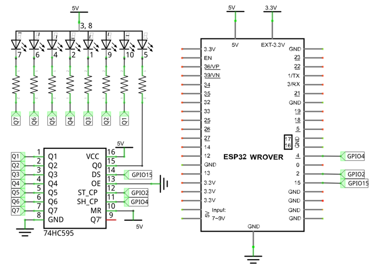
Schematic diagram |
|
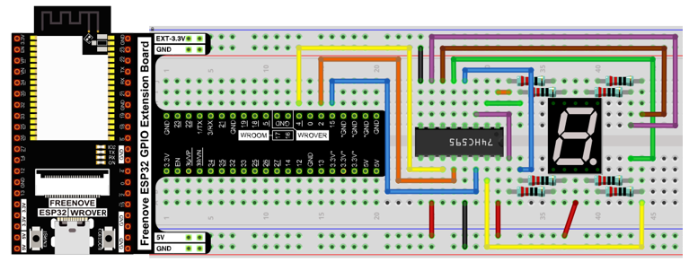
Hardware connection |
If you need any support, please contact us via: support@freenove.com
|
Sketch
In this section, the 74HC595 is used in the same way as in the previous section, but with different values transferred. We can learn how to master the digital display by sending the coded value of “0” - “F”.
Sketch_15.1_7_Segment_Display
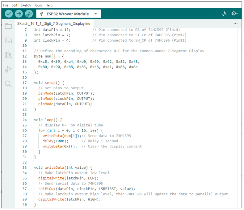
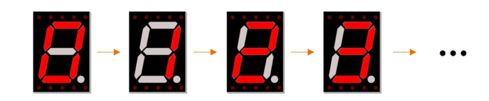
Verify and upload the code, and you’ll see a 1-bit, 7-segment display displaying 0-f in a loop.
The following is the program code:
 1/**********************************************************************
 2  Filename    : 1 Digital 7 Segment Display
 3  Description : Use 74HC595 to drive the digital display
 4  Auther      : www.freenove.com
 5  Modification: 2024/06/19
 6**********************************************************************/
 7int dataPin = 15;          // Pin connected to DS of 74HC595(Pin14)
 8int latchPin = 2;          // Pin connected to ST_CP of 74HC595(Pin12)
 9int clockPin = 4;          // Pin connected to SH_CP of 74HC595(Pin11)
10
11// Define the encoding of characters 0-F for the common-anode 7-Segment Display
12byte num[] = {
13  0xc0, 0xf9, 0xa4, 0xb0, 0x99, 0x92, 0x82, 0xf8,
14  0x80, 0x90, 0x88, 0x83, 0xc6, 0xa1, 0x86, 0x8e
15};
16
17void setup() {
18  // set pins to output
19  pinMode(latchPin, OUTPUT);
20  pinMode(clockPin, OUTPUT);
21  pinMode(dataPin, OUTPUT);
22}
23
24void loop() {
25  // display 0-F on digital tube
26  for (int i = 0; i < 16; i++) {
27    writeData(num[i]);// Send data to 74HC595
28    delay(1000);      // delay 1 second
29    writeData(0xff);  // Clear the display content
30  }
31}
32
33void writeData(int value) {
34  // Make latchPin output low level
35  digitalWrite(latchPin, LOW);
36  // Send serial data to 74HC595
37  shiftOut(dataPin, clockPin, LSBFIRST, value);
38  // Make latchPin output high level, then 74HC595 will update the data to parallel output
39  digitalWrite(latchPin, HIGH);
40}
First, put encoding of “0”- “F” into the array.
1// Define the encoding of characters 0-F for the common-anode 7-Segment Display
2byte num[] = {
3  0xc0, 0xf9, 0xa4, 0xb0, 0x99, 0x92, 0x82, 0xf8,
4  0x80, 0x90, 0x88, 0x83, 0xc6, 0xa1, 0x86, 0x8e
5};
Then, in the loop, we transfer the member of the “num” to 74HC595 by calling the writeData function, so that the digital tube displays what we want. After each display, “0xff” is used to eliminate the previous effect and prepare for the next display.
1void loop() {
2  // display 0-F on digital tube
3  for (int i = 0; i < 16; i++) {
4    writeData(num[i]);// Send data to 74HC595
5    delay(1000);      // delay 1 second
6    writeData(0xff);  // Clear the display content
7  }
8}
In the shiftOut() function, whether to use LSBFIRST or MSBFIRST as the parameter depends on the physical situation.
1void writeData(int value) {
2  // Make latchPin output low level
3  digitalWrite(latchPin, LOW);
4  // Send serial data to 74HC595
5  shiftOut(dataPin, clockPin, LSBFIRST, value);
6  // Make latchPin output high level, then 74HC595 will update the data to parallel output
7  digitalWrite(latchPin, HIGH);
8}
If you want to display the decimal point, make the highest bit of each array become 0, which can be implemented easily by num[i]&0x7f.
1shiftOut(dataPin, clockPin, LSBFIRST, value);