Chapter 26 Camera Web Server
In this section, we’ll use ESP32’s video function as an example to study.
Project 26.1 Camera Web Server
Connect ESP32 using USB and check its IP address through serial monitor. Use web page to access IP address to obtain video and image data.
Component List
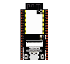
ESP32-WROVER x1
|
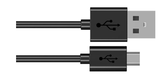
Micro USB Wire x1
|
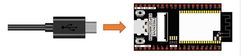
Circuit
Connect Freenove ESP32 to the computer using the USB cable.
Sketch
Sketch_26.1_As_CameraWebServer
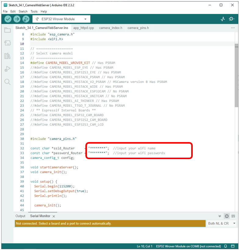
Before running the program, please modify your router’s name and password in the box shown in the illustration above to make sure that your Sketch can compile and work successfully.
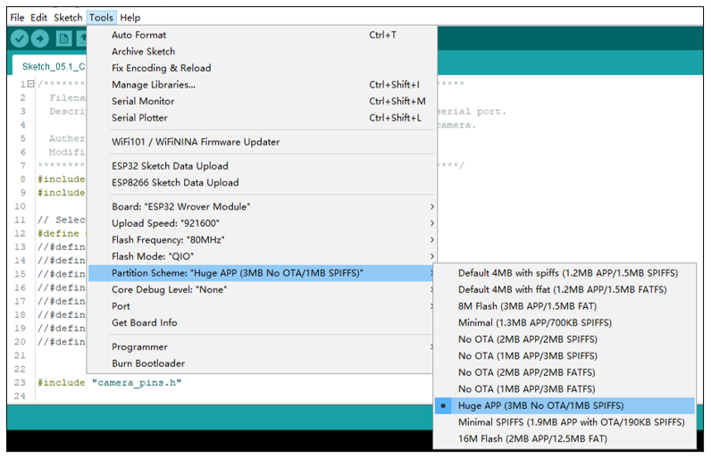
If your Arduino IDE prompts you that your sketch is out of your project’s storage space, compile the code again as configured below.
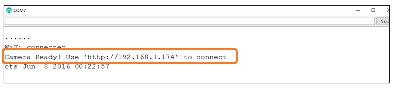
Compile and upload codes to ESP32, open the serial monitor and set the baud rate to 115200, and the serial monitor will print out a network link address.
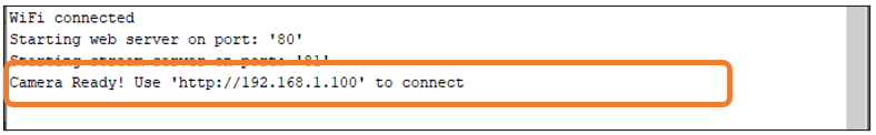
If your ESP32 has been in the process of connecting to router, but the information above has not been printed out, please re-check whether the router name and password have been entered correctly and press the reset key on ESP32-WROVER to wait for a successful connection prompt.
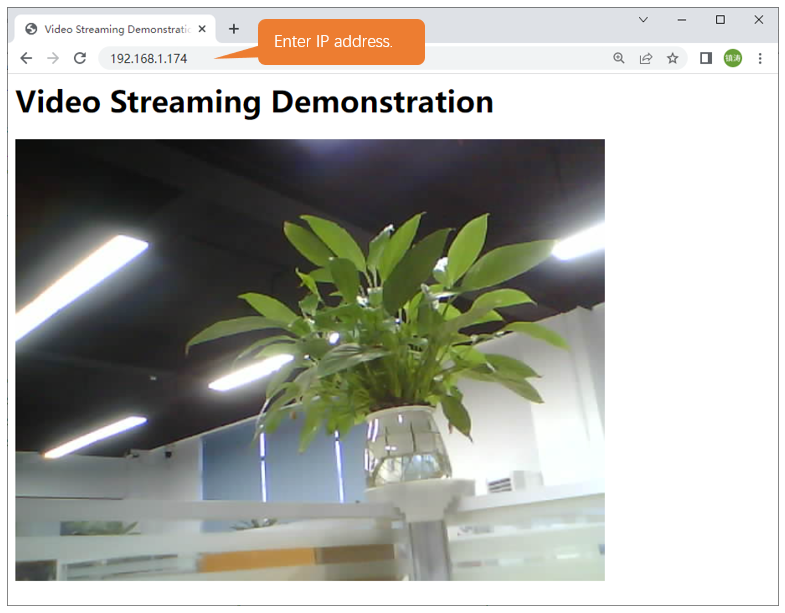
Open a web browser, enter the IP address printed by the serial monitor in the address bar, and access it.
Taking the Google browser as an example, here’s what the browser prints out after successful access to ESP32’s IP.
We recommend that the resolution not exceed VGA(640x480).
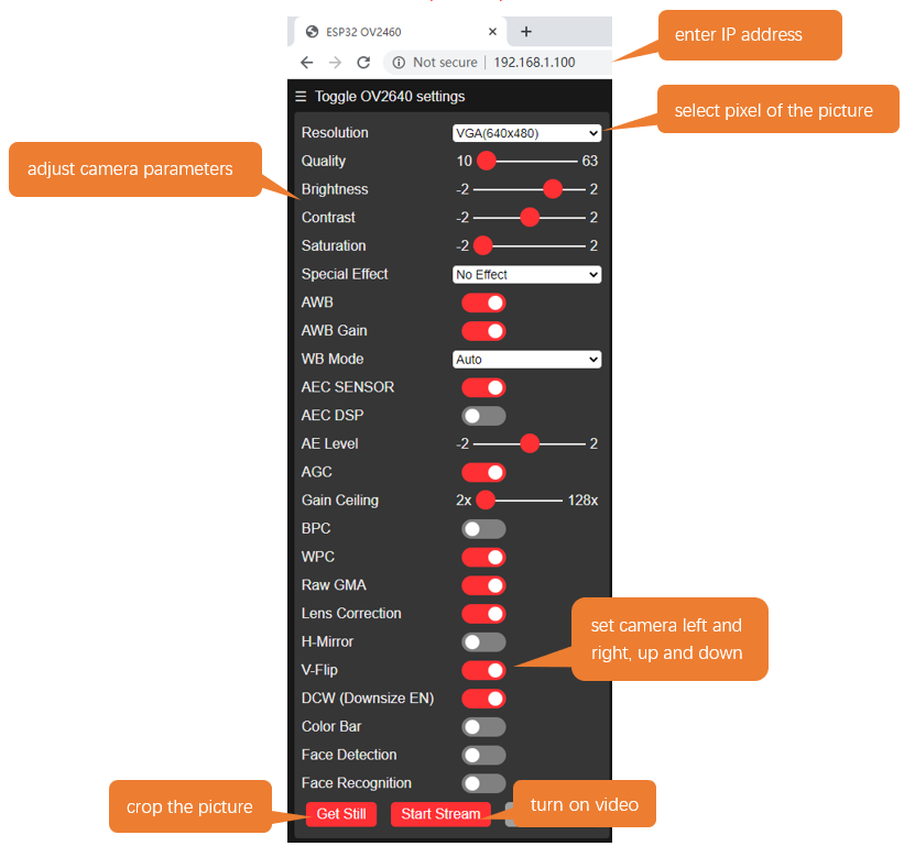
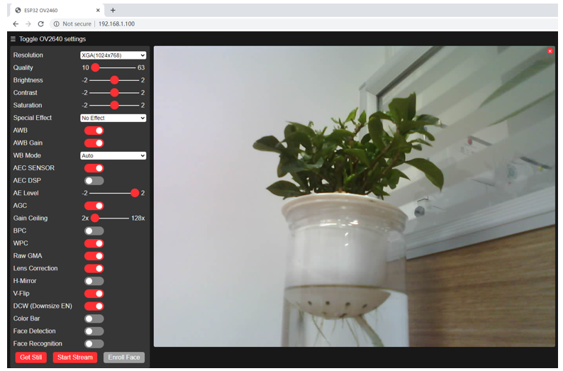
Click on Start Stream. The effect is shown in the image below.
Note
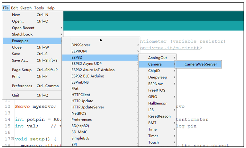
If sketch compilation fails due to ESP32 support package, follow the steps of the image to open the CameraWebServer. This sketch is the same as described in the tutorial above.
The following is the main program code. You need include other code files in the same folder when write your own code.
  1/**********************************************************************
  2  Filename    : Camera Web Serrver
  3  Description : ESP32 connects to WiFi and prints a url through a serial port.
  4                Users visit the site to view the image data ESP32 camera.
  5  Auther      : www.freenove.com
  6  Modification: 2024/06/20
  7**********************************************************************/
  8#include "esp_camera.h"
  9#include <WiFi.h>
 10#include "board_config.h"
 11
 12// ===================
 13// Select camera model
 14// ===================
 15#define CAMERA_MODEL_WROVER_KIT // Has PSRAM
 16//#define CAMERA_MODEL_ESP_EYE // Has PSRAM
 17//#define CAMERA_MODEL_ESP32S3_EYE // Has PSRAM
 18//#define CAMERA_MODEL_M5STACK_PSRAM // Has PSRAM
 19//#define CAMERA_MODEL_M5STACK_V2_PSRAM // M5Camera version B Has PSRAM
 20//#define CAMERA_MODEL_M5STACK_WIDE // Has PSRAM
 21//#define CAMERA_MODEL_M5STACK_ESP32CAM // No PSRAM
 22//#define CAMERA_MODEL_M5STACK_UNITCAM // No PSRAM
 23//#define CAMERA_MODEL_AI_THINKER // Has PSRAM
 24//#define CAMERA_MODEL_TTGO_T_JOURNAL // No PSRAM
 25// ** Espressif Internal Boards **
 26//#define CAMERA_MODEL_ESP32_CAM_BOARD
 27//#define CAMERA_MODEL_ESP32S2_CAM_BOARD
 28//#define CAMERA_MODEL_ESP32S3_CAM_LCD
 29
 30
 31#include "camera_pins.h"
 32
 33const char *ssid_Router     = "********";  //input your wifi name
 34const char *password_Router = "********";  //input your wifi passwords
 35camera_config_t config;
 36
 37void startCameraServer();
 38void camera_init();
 39
 40void setup() {
 41  Serial.begin(115200);
 42  Serial.setDebugOutput(true);
 43  Serial.println();
 44
 45  camera_init();
 46
 47  // camera init
 48  esp_err_t err = esp_camera_init(&config);
 49  if (err != ESP_OK) {
 50    Serial.printf("Camera init failed with error 0x%x", err);
 51    return;
 52  }
 53
 54  sensor_t * s = esp_camera_sensor_get();
 55  s->set_vflip(s, 0);        //1-Upside down, 0-No operation
 56  s->set_hmirror(s, 0);      //1-Reverse left and right, 0-No operation
 57  s->set_brightness(s, 1);   //up the blightness just a bit
 58  s->set_saturation(s, -1);  //lower the saturation
 59
 60  WiFi.begin(ssid_Router, password_Router);
 61  WiFi.setSleep(false);
 62  while (WiFi.status() != WL_CONNECTED) {
 63    delay(500);
 64    Serial.print(".");
 65  }
 66  Serial.println("");
 67  Serial.println("WiFi connected");
 68
 69  startCameraServer();
 70
 71  Serial.print("Camera Ready! Use 'http://");
 72  Serial.print(WiFi.localIP());
 73  Serial.println("' to connect");
 74}
 75
 76void loop() {
 77  ;
 78}
 79
 80void camera_init() {
 81  config.ledc_channel = LEDC_CHANNEL_0;
 82  config.ledc_timer = LEDC_TIMER_0;
 83  config.pin_d0 = Y2_GPIO_NUM;
 84  config.pin_d1 = Y3_GPIO_NUM;
 85  config.pin_d2 = Y4_GPIO_NUM;
 86  config.pin_d3 = Y5_GPIO_NUM;
 87  config.pin_d4 = Y6_GPIO_NUM;
 88  config.pin_d5 = Y7_GPIO_NUM;
 89  config.pin_d6 = Y8_GPIO_NUM;
 90  config.pin_d7 = Y9_GPIO_NUM;
 91  config.pin_xclk = XCLK_GPIO_NUM;
 92  config.pin_pclk = PCLK_GPIO_NUM;
 93  config.pin_vsync = VSYNC_GPIO_NUM;
 94  config.pin_href = HREF_GPIO_NUM;
 95  config.pin_sccb_sda = SIOD_GPIO_NUM;
 96  config.pin_sccb_scl = SIOC_GPIO_NUM;
 97  config.pin_pwdn = PWDN_GPIO_NUM;
 98  config.pin_reset = RESET_GPIO_NUM;
 99  config.xclk_freq_hz = 10000000;
100  config.frame_size = FRAMESIZE_QVGA;
101  config.pixel_format = PIXFORMAT_JPEG; // for streaming
102  //config.pixel_format = PIXFORMAT_RGB565; // for face detection/recognition
103  config.grab_mode = CAMERA_GRAB_WHEN_EMPTY;
104  config.fb_location = CAMERA_FB_IN_PSRAM;
105  config.jpeg_quality = 10;
106  config.fb_count = 2;
107}
Add procedure files and API interface files related to ESP32 camera.
 1#include "esp_camera.h"
 2#include <WiFi.h>
 3#include "board_config.h"
 4
 5// ===================
 6// Select camera model
 7// ===================
 8#define CAMERA_MODEL_WROVER_KIT // Has PSRAM
 9//#define CAMERA_MODEL_ESP_EYE // Has PSRAM
10//#define CAMERA_MODEL_ESP32S3_EYE // Has PSRAM
11//#define CAMERA_MODEL_M5STACK_PSRAM // Has PSRAM
12//#define CAMERA_MODEL_M5STACK_V2_PSRAM // M5Camera version B Has PSRAM
13//#define CAMERA_MODEL_M5STACK_WIDE // Has PSRAM
14//#define CAMERA_MODEL_M5STACK_ESP32CAM // No PSRAM
15//#define CAMERA_MODEL_M5STACK_UNITCAM // No PSRAM
16//#define CAMERA_MODEL_AI_THINKER // Has PSRAM
17//#define CAMERA_MODEL_TTGO_T_JOURNAL // No PSRAM
18// ** Espressif Internal Boards **
19//#define CAMERA_MODEL_ESP32_CAM_BOARD
20//#define CAMERA_MODEL_ESP32S2_CAM_BOARD
21//#define CAMERA_MODEL_ESP32S3_CAM_LCD
22
23
Enter the name and password of the router
1
2const char *ssid_Router     = "********";  //input your wifi name
Initialize serial port, set baud rate to 115200; open the debug and output function of the serial.
1void setup() {
2  Serial.begin(115200);
3  Serial.setDebugOutput(true);
Configure parameters including interface pins of the camera. Note: It is generally not recommended to change them.
 1
 2void camera_init() {
 3  config.ledc_channel = LEDC_CHANNEL_0;
 4  config.ledc_timer = LEDC_TIMER_0;
 5  config.pin_d0 = Y2_GPIO_NUM;
 6  config.pin_d1 = Y3_GPIO_NUM;
 7  config.pin_d2 = Y4_GPIO_NUM;
 8  config.pin_d3 = Y5_GPIO_NUM;
 9  config.pin_d4 = Y6_GPIO_NUM;
10  config.pin_d5 = Y7_GPIO_NUM;
11  config.pin_d6 = Y8_GPIO_NUM;
12  config.pin_d7 = Y9_GPIO_NUM;
13  config.pin_xclk = XCLK_GPIO_NUM;
14  config.pin_pclk = PCLK_GPIO_NUM;
15  config.pin_vsync = VSYNC_GPIO_NUM;
16  config.pin_href = HREF_GPIO_NUM;
17  config.pin_sccb_sda = SIOD_GPIO_NUM;
18  config.pin_sccb_scl = SIOC_GPIO_NUM;
19  config.pin_pwdn = PWDN_GPIO_NUM;
20  config.pin_reset = RESET_GPIO_NUM;
21  config.xclk_freq_hz = 10000000;
22  config.frame_size = FRAMESIZE_QVGA;
23  config.pixel_format = PIXFORMAT_JPEG; // for streaming
24  //config.pixel_format = PIXFORMAT_RGB565; // for face detection/recognition
25  config.grab_mode = CAMERA_GRAB_WHEN_EMPTY;
26  config.fb_location = CAMERA_FB_IN_PSRAM;
27  config.jpeg_quality = 10;
28  config.fb_count = 2;
ESP32 connects to the router and prints a successful connection prompt. If it has not been successfully connected, press the reset key on the ESP32-WROVER.
1
2WiFi.begin(ssid_Router, password_Router);
3WiFi.setSleep(false);
4while (WiFi.status() != WL_CONNECTED) {
5  delay(500);
6  Serial.print(".");
7}
8Serial.println("");
Open the video streams server function of the camera and print its IP address via serial port.
1
2startCameraServer();
3
4Serial.print("Camera Ready! Use 'http://");
5Serial.print(WiFi.localIP());
Configure the display image information of the camera.
The set_vflip() function sets whether the image is flipped 180°, with 0 for no flip and 1 for flip 180°.
The set_brightness() function sets the brightness of the image, with values ranging from -2 to 2.
The set_saturation() function sets the color saturation of the image, with values ranging from -2 to 2.
1
2sensor_t * s = esp_camera_sensor_get();
3s->set_vflip(s, 0);        //1-Upside down, 0-No operation
4s->set_hmirror(s, 0);      //1-Reverse left and right, 0-No operation
5s->set_brightness(s, 1);   //up the blightness just a bit
Modify the resolution and sharpness of the images captured by the camera. The sharpness ranges from 10 to 63, and the smaller the number, the sharper the picture. The larger the number, the blurrier the picture. Please refer to the table below.
config.frame_size = FRAMESIZE_VGA;
config.jpeg_quality = 10;
Reference
Image resolution |
Sharpness |
Image resolution |
Sharpness |
|---|---|---|---|
FRAMESIZE_96x96 |
96x96 |
FRAMESIZE_HVGA |
480x320 |
FRAMESIZE_QQVGA |
160x120 |
FRAMESIZE_VGA |
640x480 |
FRAMESIZE_QCIF |
176x144 |
FRAMESIZE_SVGA |
800x600 |
FRAMESIZE_HQVGA |
240x176 |
FRAMESIZE_XGA |
1024x768 |
FRAMESIZE_240x240 |
240x240 |
FRAMESIZE_HD |
1280x720 |
FRAMESIZE_QVGA |
320x240 |
FRAMESIZE_SXGA |
1280x1024 |
FRAMESIZE_CIF |
400x296 |
FRAMESIZE_UXGA |
1600x1200 |
We recommend that the resolution not exceed VGA(640x480).
Project 26.2 Video Web Server
Connect to ESP32 using USB and view its IP address through a serial monitor. Access IP addresses through web pages to obtain real-time video data.
Component List
ESP32-WROVER x1
|
Micro USB Wire x1
|
Circuit
Connect Freenove ESP32 to the computer using the USB cable.
Sketch
Sketch_26.2_As_VideoWebServer
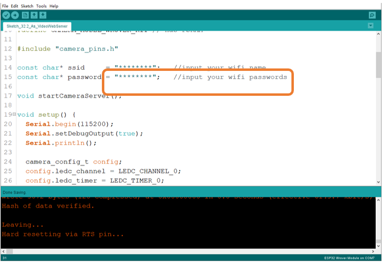
Before running the program, please modify your router’s name and password in the box shown in the illustration above to make sure that your Sketch can compile and work successfully.
Compile and upload codes to ESP32, open the serial monitor and set the baud rate to 115200, and the serial monitor will print out a network link address.
If your ESP32 has been in the process of connecting to router, but the information above has not been printed out, please re-check whether the router name and password have been entered correctly and press the reset key on ESP32-WROVER to wait for a successful connection prompt.
Open a web browser, enter the IP address printed by the serial monitor in the address bar, and access it.
Taking the Google browser as an example, here’s what the browser prints out after successful access to ESP32’s IP.
The effect is shown in the image below.
The following is the main program code. You need include other code files in the same folder when write your own code.
 1#include "esp_camera.h"
 2#include <WiFi.h>
 3//
 4// WARNING!!! PSRAM IC required for UXGA resolution and high JPEG quality
 5//            Ensure ESP32 Wrover Module or other board with PSRAM is selected
 6//            Partial images will be transmitted if image exceeds buffer size
 7//
 8
 9// Select camera model
10#define CAMERA_MODEL_WROVER_KIT // Has PSRAM
11
12#include "camera_pins.h"
13
14const char* ssid     = "********";   //input your wifi name
15const char* password = "********";   //input your wifi passwords
16
17void startCameraServer();
18
19void setup() {
20  Serial.begin(115200);
21  Serial.setDebugOutput(true);
22  Serial.println();
23
24  camera_config_t config;
25  config.ledc_channel = LEDC_CHANNEL_0;
26  config.ledc_timer = LEDC_TIMER_0;
27  config.pin_d0 = Y2_GPIO_NUM;
28  config.pin_d1 = Y3_GPIO_NUM;
29  config.pin_d2 = Y4_GPIO_NUM;
30  config.pin_d3 = Y5_GPIO_NUM;
31  config.pin_d4 = Y6_GPIO_NUM;
32  config.pin_d5 = Y7_GPIO_NUM;
33  config.pin_d6 = Y8_GPIO_NUM;
34  config.pin_d7 = Y9_GPIO_NUM;
35  config.pin_xclk = XCLK_GPIO_NUM;
36  config.pin_pclk = PCLK_GPIO_NUM;
37  config.pin_vsync = VSYNC_GPIO_NUM;
38  config.pin_href = HREF_GPIO_NUM;
39  config.pin_sccb_sda = SIOD_GPIO_NUM;
40  config.pin_sccb_scl = SIOC_GPIO_NUM;
41  config.pin_pwdn = PWDN_GPIO_NUM;
42  config.pin_reset = RESET_GPIO_NUM;
43  config.xclk_freq_hz = 10000000;
44  config.pixel_format = PIXFORMAT_JPEG;
45
46  // if PSRAM IC present, init with UXGA resolution and higher JPEG quality
47  //                      for larger pre-allocated frame buffer.
48  if(psramFound()){
49    config.frame_size = FRAMESIZE_VGA;
50    config.jpeg_quality = 10;
51    config.fb_count = 2;
52  } else {
53    config.frame_size = FRAMESIZE_SVGA;
54    config.jpeg_quality = 12;
55    config.fb_count = 1;
56  }
57
58  // camera init
59  esp_err_t err = esp_camera_init(&config);
60  if (err != ESP_OK) {
61    Serial.printf("Camera init failed with error 0x%x", err);
62    return;
63  }
64
65  sensor_t * s = esp_camera_sensor_get();
66  // drop down frame size for higher initial frame rate
67  s->set_framesize(s, FRAMESIZE_VGA);
68
69  WiFi.begin(ssid, password);
70
71  while (WiFi.status() != WL_CONNECTED) {
72    delay(500);
73    Serial.print(".");
74  }
75  Serial.println("");
76  Serial.println("WiFi connected");
77
78  startCameraServer();
79
80  Serial.print("Camera Ready! Use 'http://");
81  Serial.print(WiFi.localIP());
82  Serial.println("' to connect");
83}
84
85void loop() {
86  // put your main code here, to run repeatedly:
87  delay(10000);
88}
Configure parameters including interface pins of the camera. Note: It is generally not recommended to change them.
 1camera_config_t config;
 2config.ledc_channel = LEDC_CHANNEL_0;
 3config.ledc_timer = LEDC_TIMER_0;
 4config.pin_d0 = Y2_GPIO_NUM;
 5config.pin_d1 = Y3_GPIO_NUM;
 6config.pin_d2 = Y4_GPIO_NUM;
 7config.pin_d3 = Y5_GPIO_NUM;
 8config.pin_d4 = Y6_GPIO_NUM;
 9config.pin_d5 = Y7_GPIO_NUM;
10config.pin_d6 = Y8_GPIO_NUM;
11config.pin_d7 = Y9_GPIO_NUM;
12config.pin_xclk = XCLK_GPIO_NUM;
13config.pin_pclk = PCLK_GPIO_NUM;
14config.pin_vsync = VSYNC_GPIO_NUM;
15config.pin_href = HREF_GPIO_NUM;
16config.pin_sccb_sda = SIOD_GPIO_NUM;
17config.pin_sccb_scl = SIOC_GPIO_NUM;
18config.pin_pwdn = PWDN_GPIO_NUM;
19config.pin_reset = RESET_GPIO_NUM;
20config.xclk_freq_hz = 10000000;
21config.pixel_format = PIXFORMAT_JPEG;
ESP32 connects to the router and prints a successful connection prompt. If it has not been successfully connected, press the reset key on the ESP32-WROVER.
1WiFi.begin(ssid, password);
2
3while (WiFi.status() != WL_CONNECTED) {
4  delay(500);
5  Serial.print(".");
6}
7Serial.println("");
8Serial.println("WiFi connected");
Open the video streams server function of the camera and print its IP address via serial port.
1startCameraServer();
2
3Serial.print("Camera Ready! Use 'http://");
4Serial.print(WiFi.localIP());
5Serial.println("' to connect");