Chapter 31 Soldering Circuit Board
Project 31.1 Soldering a Buzzer
We have tried to use a buzzer in a previous chapter, and now we will solder a circuit that when the button is pressed, the buzzer sounds.
This circuit does not need programming and can work when it is powered on. And when the button is not pressed, there is no power consumption.
You can install it on your bike, bedroom door or any other places where it is needed.
Component List
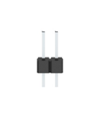
Pin header x2 |
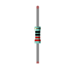
Resistor 220Ω x1 |
|
|
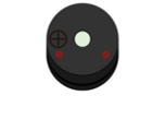
Active buzzer x1 |
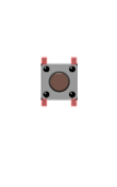
Push button x1 |
|
|
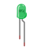
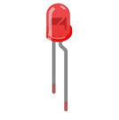
LED x1 |
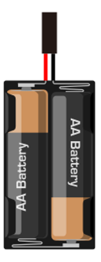
AA Battery Holder x1 |
|
|
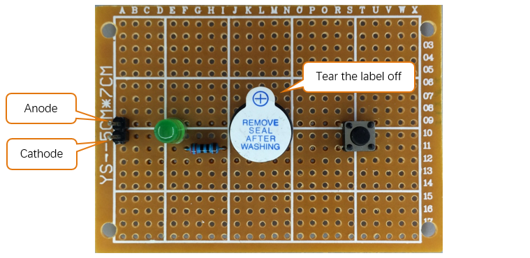
Circuit
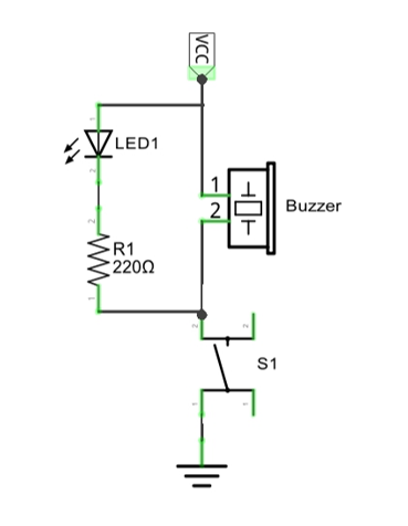
We will solder the following circuit on the main board.
Schematic diagram |
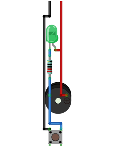
Hardware connection If you need any support, please feel free to contact us via: |
|
|
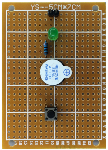
Soldering the Circuit
Insert the components on the main board and solder the circuit on its back.
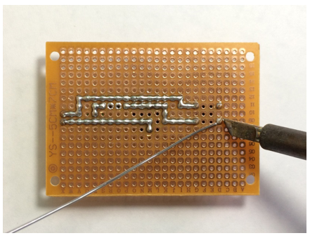
rendering after soldering:
Front |
Back |
|---|---|
|
|
Testing circuit
Connect the circuit board to power supply (3~5V). You can use ESP32 board or battery box as the power supply.
Press the push button after connecting the power, and then the buzzer will make a sound.
Project 31.2 Soldering a Flowing Water Light
From previous chapter, we have learned to make a flowing water light with LED. Now, we will solder a circuit board, and use the improved code to make a more interesting flowing water light.
Component List
Pin header x5
|
Resistor 220Ω x8
|
LED x1
|
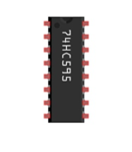
74HC595 x1
|
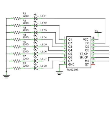
Circuit
Solder the following circuit on the main board.
Schematic diagram |
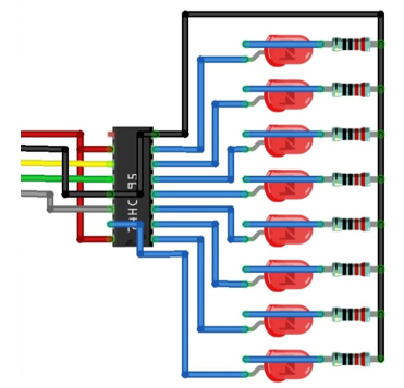
Hardware connection |
|---|---|
|
|
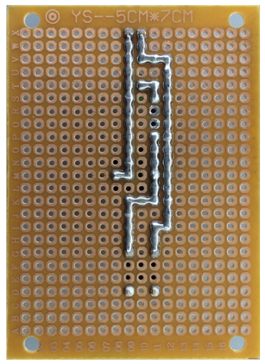
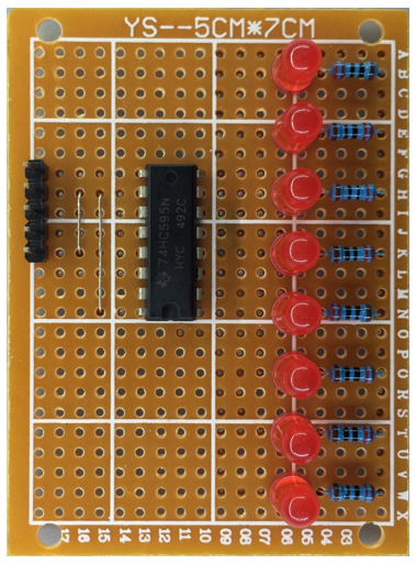
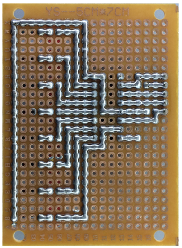
Soldering the Circuit
Insert the components on the main board and solder the circuit on its back.
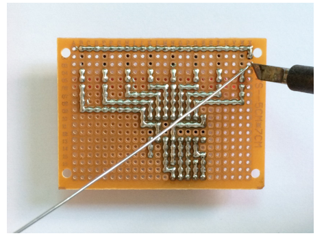
Rendering after soldering:
Front |
Back |
|---|---|
|
|
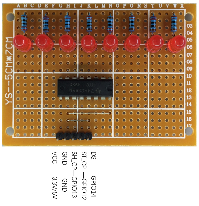
Connecting the Circuit
Connect the board to ESP32 with jumper wire in the following way.
Code
The following is the program code:
 1import time
 2from my74HC595 import Chip74HC595
 3
 4chip = Chip74HC595(14,12,13)
 5# ESP32-14: 74HC595-DS(14)
 6# ESP32-12: 74HC595-STCP(12)
 7# ESP32-13: 74HC595-SHCP(11)
 8
 9while True:
10    x=0x01
11    for count in range(8):
12        chip.shiftOut(1,x)  #High bit is sent first
13        x=x<<1
14        time.sleep_ms(300)
15    x=0x01
16    for count in range(8):
17        chip.shiftOut(0,x)  #Low bit is sent first
18        x=x<<1
19        time.sleep_ms(300)