36. Chapter USB
In this chapter, we will learn some simple examples of USB ports.
36.1. Project USB Serial Example
In this project, we have created a USB-to-serial bridge, allowing communication with the ESP32’s hardware serial port via the USB interface.
36.1.1. Component List
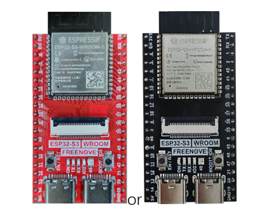
ESP32-S3 WROOM x1
|
USB cable x1
|
36.1.2. Power
ESP32-S3 WROOM needs 5v power supply. In this tutorial, we need connect ESP32-S3 WROOM to computer via USB cable to power it and program it. We can also use other 5v power source to power it.
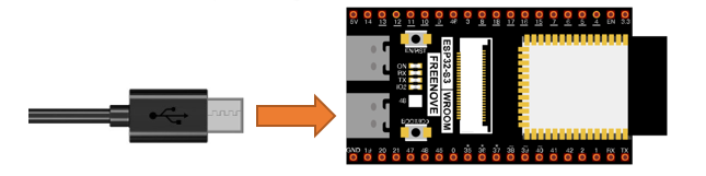
In the following projects, we only use USB cable to power ESP32-S3 WROOM by default.
In the whole tutorial, we don’t use T extension to power ESP32-S3 WROOM. So 5V and 3.3V (includeing EXT 3.3V) on the extension board are provided by ESP32-S3 WROOM.
We can also use DC jack of extension board to power ESP32-S3 WROOM. In this way, 5v and EXT 3.3v on extension board are provided by external power resource.
36.1.3. Component knowledge
36.1.3.1. Difference between USB-OTG and USB-UART Interfaces
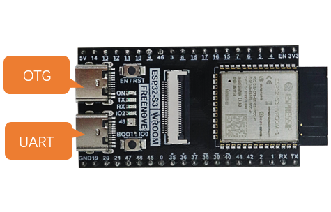
As shown in the figure below, our development board includes two USB interfaces: USB-OTG and USB-UART.
Among them, the USB-UART interface is connected to the on-board USB-to-TTL circuit, which is then connected to the ESP32-S3 module’s serial port pins (TX: GPIO43 and RX: GPIO44).
The USB-OTG interface is directly connected to the ESP32-S3 module’s USB pins (USB_D-: GPIO19 and USB_D+: GPIO20).
USB-OTG |
The USB-OTG interface allows code uploads and can simulate peripherals such as a mouse, keyboard, computer controller, or gamepad based on the provided code. |
|
USB-UART |
The USB-UART interface is primarily used for code upload and serial communication. It is more stable and reliable than USB-OTG. |
36.1.3.2. Enabling USB-OTG
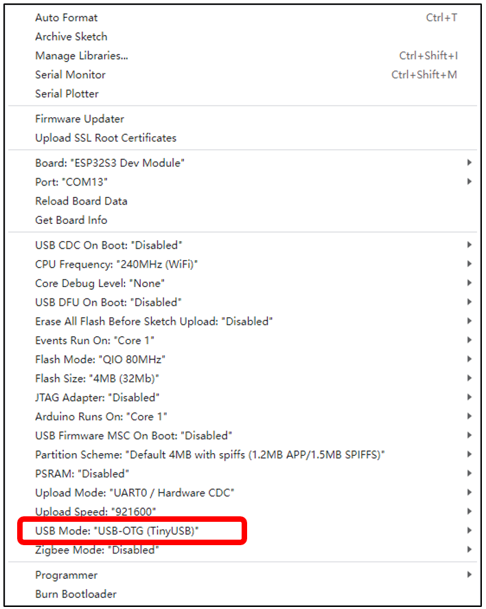
Please note: To use the USB function of the ESP32-S3, you must enable the configuration boxed below. Otherwise, the code will not take effect.
36.1.4. Sketch
36.1.4.1. Sketch USBSerial
Click the icon to compile and upload the sketch to the ESP32S3.
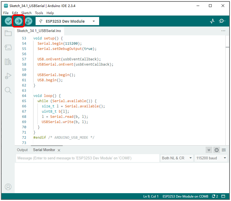
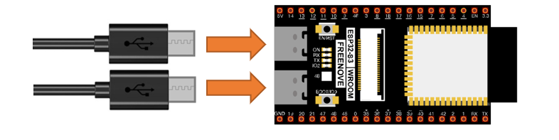
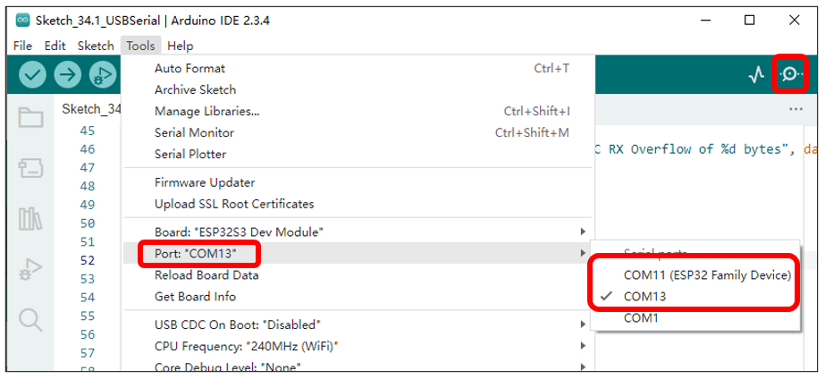
Note: You will need to prepare an additional USB cable to connect both USB interfaces simultaneously.
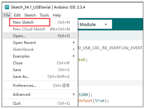
You can open a new interface by clicking File -> New Sketch.
Select the COM port numbers corresponding to USB-UART and USB-OTG respectively in the two interfaces, open the serial monitors, and set the baud rate to 115200.
You can input any content in the serial monitor of the USB-UART port and press Enter. The ESP32-S3 will detect the data input from the USB-UART, package it, and send it to the USB-OTG. Similarly, when the ESP32-S3 detects data input from the USB-OTG, it will package the data and forward it to the USB-UART.
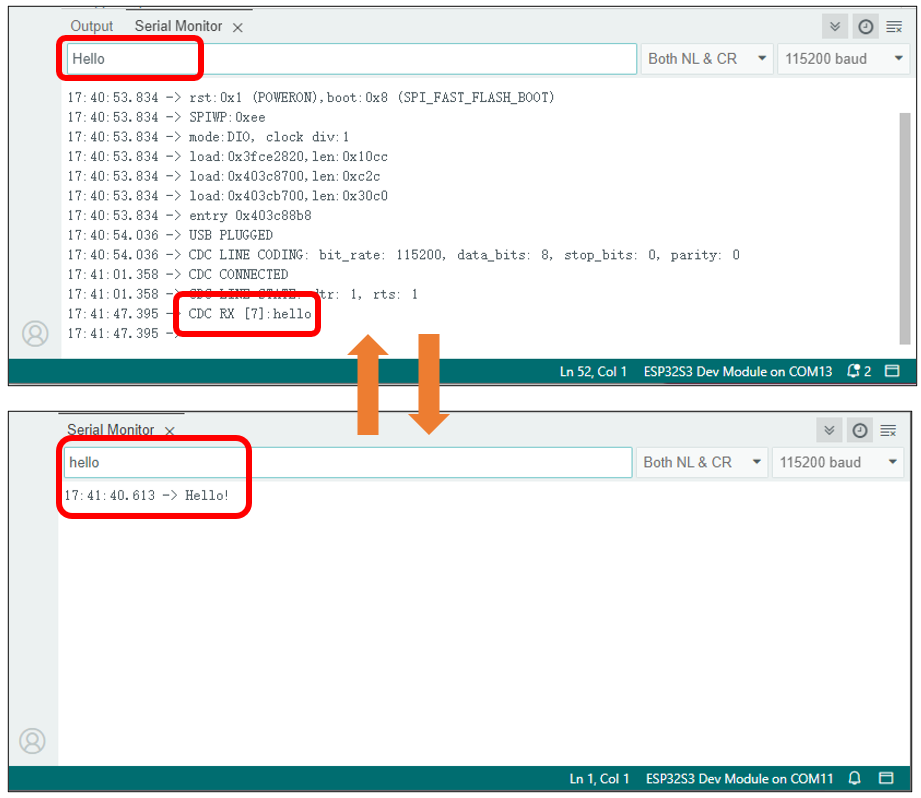
The communication between USB-OTG and USB-UART is similar to that described in the Serial Communication section.
The following is the program code:
 1#ifndef ARDUINO_USB_MODE
 2#error This ESP32 SoC has no Native USB interface
 3#elif ARDUINO_USB_MODE == 1
 4#warning This sketch should be used when USB is in OTG mode
 5void setup() {}
 6void loop() {}
 7#else
 8#include "USB.h"
 9
10#if !ARDUINO_USB_CDC_ON_BOOT
11USBCDC USBSerial;
12#endif
13
14static void usbEventCallback(void *arg, esp_event_base_t event_base, int32_t event_id, void *event_data) {
15  if (event_base == ARDUINO_USB_EVENTS) {
16    arduino_usb_event_data_t *data = (arduino_usb_event_data_t *)event_data;
17    switch (event_id) {
18      case ARDUINO_USB_STARTED_EVENT: Serial.println("USB PLUGGED"); break;
19      case ARDUINO_USB_STOPPED_EVENT: Serial.println("USB UNPLUGGED"); break;
20      case ARDUINO_USB_SUSPEND_EVENT: Serial.printf("USB SUSPENDED: remote_wakeup_en: %u\n", data->suspend.remote_wakeup_en); break;
21      case ARDUINO_USB_RESUME_EVENT:  Serial.println("USB RESUMED"); break;
22
23      default: break;
24    }
25  } else if (event_base == ARDUINO_USB_CDC_EVENTS) {
26    arduino_usb_cdc_event_data_t *data = (arduino_usb_cdc_event_data_t *)event_data;
27    switch (event_id) {
28      case ARDUINO_USB_CDC_CONNECTED_EVENT:    Serial.println("CDC CONNECTED"); break;
29      case ARDUINO_USB_CDC_DISCONNECTED_EVENT: Serial.println("CDC DISCONNECTED"); break;
30      case ARDUINO_USB_CDC_LINE_STATE_EVENT:   Serial.printf("CDC LINE STATE: dtr: %u, rts: %u\n", data->line_state.dtr, data->line_state.rts); break;
31      case ARDUINO_USB_CDC_LINE_CODING_EVENT:
32        Serial.printf(
33          "CDC LINE CODING: bit_rate: %lu, data_bits: %u, stop_bits: %u, parity: %u\n", data->line_coding.bit_rate, data->line_coding.data_bits,
34          data->line_coding.stop_bits, data->line_coding.parity
35        );
36        break;
37      case ARDUINO_USB_CDC_RX_EVENT:
38        Serial.printf("CDC RX [%u]:", data->rx.len);
39        {
40          uint8_t buf[data->rx.len];
41          size_t len = USBSerial.read(buf, data->rx.len);
42          Serial.write(buf, len);
43        }
44        Serial.println();
45        break;
46      case ARDUINO_USB_CDC_RX_OVERFLOW_EVENT: Serial.printf("CDC RX Overflow of %d bytes", data->rx_overflow.dropped_bytes); break;
47
48      default: break;
49    }
50  }
51}
52
53void setup() {
54  Serial.begin(115200);
55  Serial.setDebugOutput(true);
56
57  USB.onEvent(usbEventCallback);
58  USBSerial.onEvent(usbEventCallback);
59
60  USBSerial.begin();
61  USB.begin();
62}
63
64void loop() {
65  while (Serial.available()) {
66    size_t l = Serial.available();
67    uint8_t b[l];
68    l = Serial.read(b, l);
69    USBSerial.write(b, l);
70  }
71}
72#endif /* ARDUINO_USB_MODE */
Check the configuration information. If the configuration is incorrect, the code will not run properly. Please pay attention to the prompt messages during compilation.
 1#ifndef ARDUINO_USB_MODE
 2#error This ESP32 SoC has no Native USB interface
 3#elif ARDUINO_USB_MODE == 1
 4#warning This sketch should be used when USB is in OTG mode
 5void setup() {}
 6void loop() {}
 7#else
 8#include "USB.h"
 9
10#if !ARDUINO_USB_CDC_ON_BOOT
11USBCDC USBSerial;
12#endif
The USB callback function is primarily used to handle USB events, CDC events, data reception events, and so on.
 1static void usbEventCallback(void *arg, esp_event_base_t event_base, int32_t event_id, void *event_data) {
 2  if (event_base == ARDUINO_USB_EVENTS) {
 3    arduino_usb_event_data_t *data = (arduino_usb_event_data_t *)event_data;
 4    switch (event_id) {
 5      case ARDUINO_USB_STARTED_EVENT: Serial.println("USB PLUGGED"); break;
 6      case ARDUINO_USB_STOPPED_EVENT: Serial.println("USB UNPLUGGED"); break;
 7      case ARDUINO_USB_SUSPEND_EVENT: Serial.printf("USB SUSPENDED: remote_wakeup_en: %u\n", data->suspend.remote_wakeup_en); break;
 8      case ARDUINO_USB_RESUME_EVENT:  Serial.println("USB RESUMED"); break;
 9
10      default: break;
11    }
12  } else if (event_base == ARDUINO_USB_CDC_EVENTS) {
13    arduino_usb_cdc_event_data_t *data = (arduino_usb_cdc_event_data_t *)event_data;
14    switch (event_id) {
15      case ARDUINO_USB_CDC_CONNECTED_EVENT:    Serial.println("CDC CONNECTED"); break;
16      case ARDUINO_USB_CDC_DISCONNECTED_EVENT: Serial.println("CDC DISCONNECTED"); break;
17      case ARDUINO_USB_CDC_LINE_STATE_EVENT:   Serial.printf("CDC LINE STATE: dtr: %u, rts: %u\n", data->line_state.dtr, data->line_state.rts); break;
18      case ARDUINO_USB_CDC_LINE_CODING_EVENT:
19        Serial.printf(
20          "CDC LINE CODING: bit_rate: %lu, data_bits: %u, stop_bits: %u, parity: %u\n", data->line_coding.bit_rate, data->line_coding.data_bits,
21          data->line_coding.stop_bits, data->line_coding.parity
22        );
23        break;
24      case ARDUINO_USB_CDC_RX_EVENT:
25        Serial.printf("CDC RX [%u]:", data->rx.len);
26        {
27          uint8_t buf[data->rx.len];
28          size_t len = USBSerial.read(buf, data->rx.len);
29          Serial.write(buf, len);
30        }
31        Serial.println();
32        break;
33      case ARDUINO_USB_CDC_RX_OVERFLOW_EVENT: Serial.printf("CDC RX Overflow of %d bytes", data->rx_overflow.dropped_bytes); break;
34
35      default: break;
36    }
37  }
38}
Initialize the serial port, configure callback functions for both USB and USBSerial, and then initialize USBSerial and USB. Note that USB.begin() should be placed last during initialization.
 1void setup() {
 2  Serial.begin(115200);
 3  Serial.setDebugOutput(true);
 4
 5  USB.onEvent(usbEventCallback);
 6  USBSerial.onEvent(usbEventCallback);
 7
 8  USBSerial.begin();
 9  USB.begin();
10}
If data is received on the USB-UART interface, obtain the length of the data in the buffer, create an array, read the data from the buffer into the array, and then send the data out via the USB-OTG interface.
1void loop() {
2  while (Serial.available()) {
3    size_t l = Serial.available();
4    uint8_t b[l];
5    l = Serial.read(b, l);
6    USBSerial.write(b, l);
7  }
8}
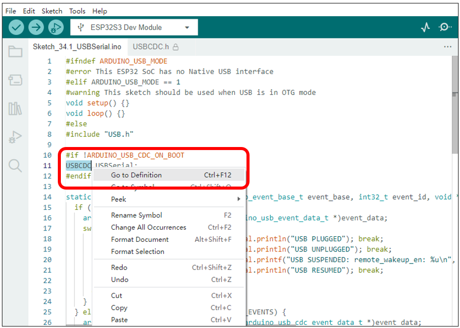
If you wish to learn more about USBSerial, you can select it in the code, right-click, and choose “Go to Definition”.
36.2. Project USB Mouse Example
In this project, we will use the USB-OTG of the ESP32-S3 to emulate a computer’s mouse functionality, allowing the ESP32-S3 to control the position and actions of the mouse.
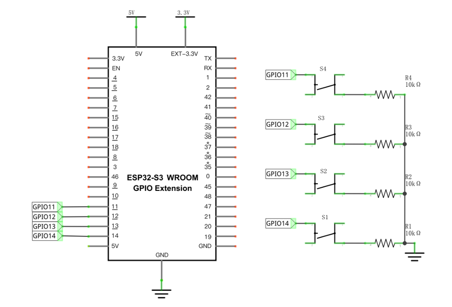
36.2.1. Component List
ESP32-S3 WROOM x1
|
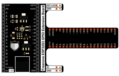
GPIO Extension Board x1
|
||
Breadboard x1
|
|||
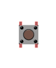
Push button x4
|
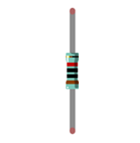
Resistor 10kΩ x4
|
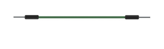
Jumper M/M x5
|
|

36.2.1.1. Power
ESP32-S3 WROOM needs 5V power supply.
In this tutorial, we connect ESP32-S3 WROOM’s USB-UART to computer via USB cable to power and program it.
After uploading the code, you can also use other 5V power source to power it.
In the following projects, we only use USB cable to power ESP32-S3 WROOM by default.
In the whole tutorial, we don’t use DC jack on the T extension board to power ESP32-S3 WROOM, so 5V and 3.3V (including EXT 3.3V) on the extension board are provided by ESP32-S3 WROOM.
If power supply is connected to the DC jack of extension board to power ESP32-S3 WROOM, the extension board’s 5V and EXT 3.3V are provided by external power resource.
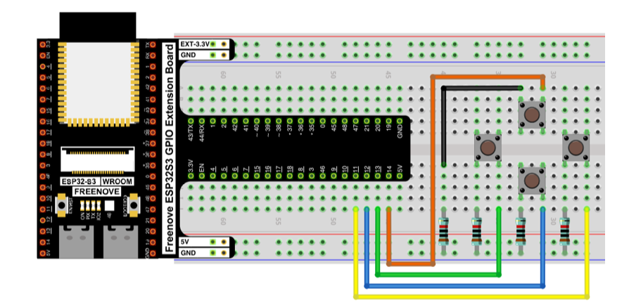
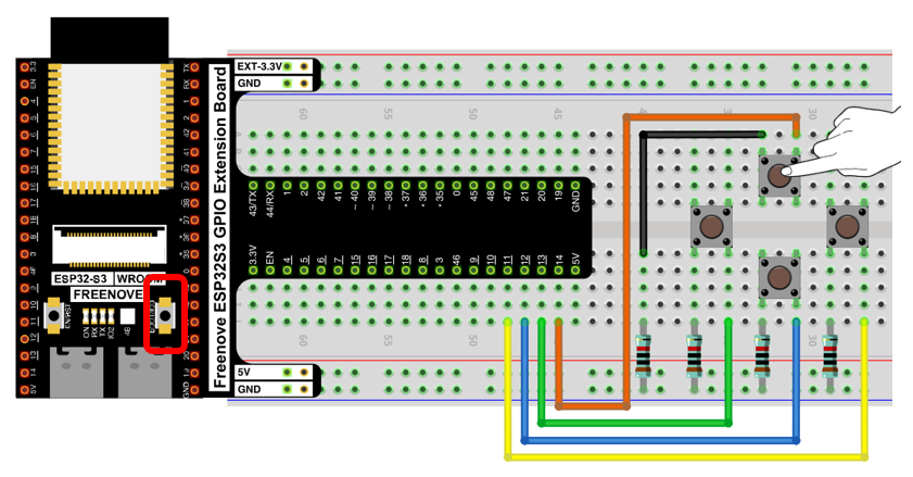
36.2.2. Circuit
Schematic diagram
|
Hardware connection. If you need any support, please feel free to contact us via: support@freenove.com
|
36.2.3. Sketch
36.2.3.1. Sketch_MouseControl
Compile and upload the code to ESP32S3.
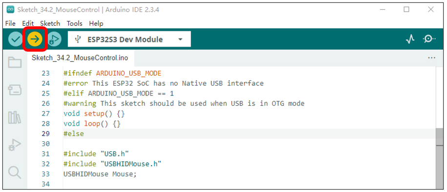
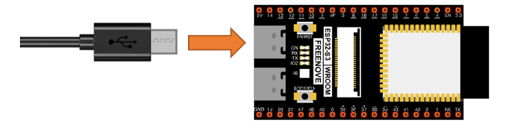
Important note: Upon the code finishes uploading, connect the USB cable to the USB-OTG interface.
When the button is pressed, the ESP32-S3 emulates the movement of a mouse on the computer screen.
When the onboard IO0 button is pressed, the ESP32-S3 emulates a left mouse click.
The following is the program code:
1/*
2 ButtonMouseControl
3
4 Controls the mouse from five pushbuttons on an Arduino Leonardo, Micro or Due.
5
6 Hardware:
7 - five pushbuttons attached to D12, D13, D14, D15, D0
8
9 The mouse movement is always relative. This sketch reads four pushbuttons,
10 and uses them to set the movement of the mouse.
11
12 WARNING: When you use the Mouse.move() command, the Arduino takes over your
13 mouse! Make sure you have control before you use the mouse commands.
14
15 created 15 Mar 2012
16 modified 27 Mar 2012
17 by Tom Igoe
18
19 This example code is in the public domain.
20
21 http://www.arduino.cc/en/Tutorial/ButtonMouseControl
22*/
23#ifndef ARDUINO_USB_MODE
24#error This ESP32 SoC has no Native USB interface
25#elif ARDUINO_USB_MODE == 1
26#warning This sketch should be used when USB is in OTG mode
27void setup() {}
28void loop() {}
29#else
30
31#include "USB.h"
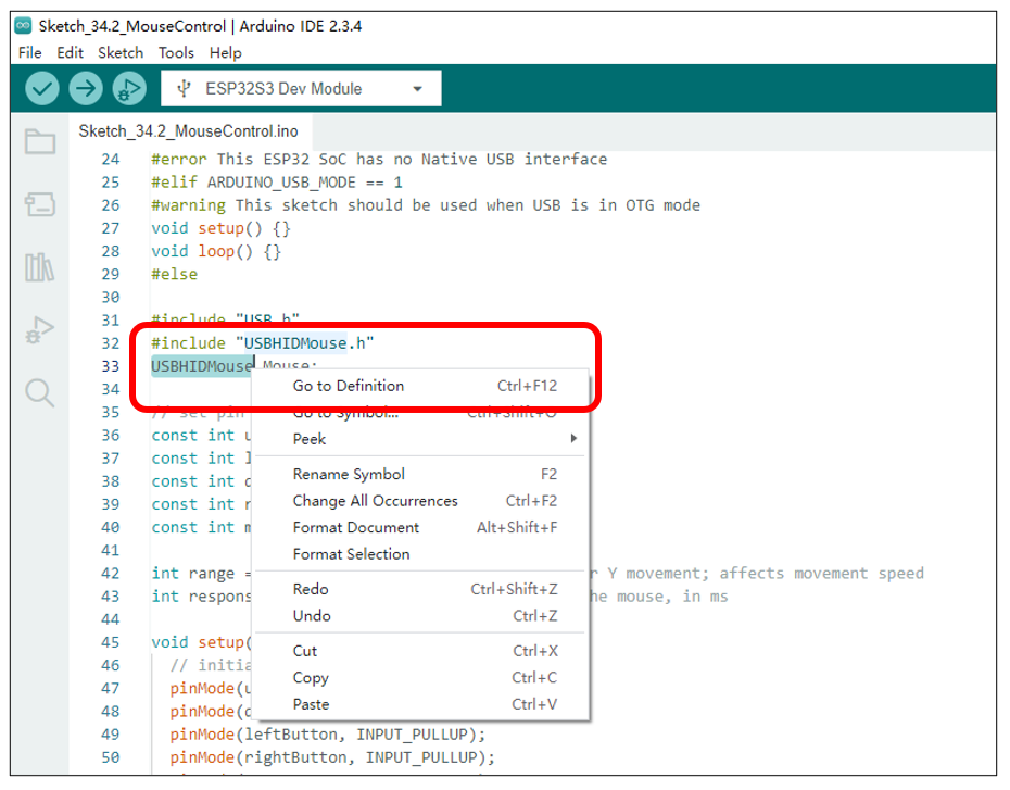
32#include "USBHIDMouse.h"
33USBHIDMouse Mouse;
34
35// set pin numbers for the five buttons:
36const int upButton = 14;
37const int leftButton = 13;
38const int downButton = 12;
39const int rightButton = 11;
40const int mouseButton = 0;
41
42int range = 5; // output range of X or Y movement; affects movement speed
43int responseDelay = 10; // response delay of the mouse, in ms
44
45void setup() {
46 // initialize the buttons' inputs:
47 pinMode(upButton, INPUT_PULLUP);
48 pinMode(downButton, INPUT_PULLUP);
49 pinMode(leftButton, INPUT_PULLUP);
50 pinMode(rightButton, INPUT_PULLUP);
51 pinMode(mouseButton, INPUT_PULLUP);
52 // initialize mouse control:
53 Mouse.begin();
54 USB.begin();
55}
56
57void loop() {
58 // read the buttons:
59 int upState = digitalRead(upButton);
60 int downState = digitalRead(downButton);
61 int rightState = digitalRead(rightButton);
62 int leftState = digitalRead(leftButton);
63 int clickState = digitalRead(mouseButton);
64
65 // calculate the movement distance based on the button states:
66 int xDistance = (leftState - rightState) * range;
67 int yDistance = (upState - downState) * range;
68
69 // if X or Y is non-zero, move:
70 if ((xDistance != 0) || (yDistance != 0)) {
71 Mouse.move(xDistance, yDistance, 0);
72 }
73
74 // if the mouse button is pressed:
75 if (clickState == LOW) {
76 // if the mouse is not pressed, press it:
77 if (!Mouse.isPressed(MOUSE_LEFT)) {
78 Mouse.press(MOUSE_LEFT);
79 }
80 }
81 // else the mouse button is not pressed:
82 else {
83 // if the mouse is pressed, release it:
84 if (Mouse.isPressed(MOUSE_LEFT)) {
85 Mouse.release(MOUSE_LEFT);
86 }
87 }
88
89 // a delay so the mouse doesn't move too fast:
90 delay(responseDelay);
91}
92#endif /* ARDUINO_USB_MODE */
Verify the configuration settings. If the configuration is incorrect, the program will not execute as expected. Please review the compilation prompts for details.
1#ifndef ARDUINO_USB_MODE
2#error This ESP32 SoC has no Native USB interface
3#elif ARDUINO_USB_MODE == 1
4#warning This sketch should be used when USB is in OTG mode
5void setup() {}
6void loop() {}
7#else
Header files related to USB HID mouse functionality and the instantiation of a mouse class object. The methods in the USBHIDMouse class operate using a relative coordinate system by default.
1#include "USB.h"
2#include "USBHIDMouse.h"
3USBHIDMouse Mouse;
USB mouse and USB driver initialization. Note that USB.begin() should be placed last during the initialization sequence.
1Mouse.begin();
2USB.begin();
Read the state of the button and, based on its status, have the ESP32-S3’s USB-OTG emulate mouse movement signals.
 1// read the buttons:
 2int upState = digitalRead(upButton);
 3int downState = digitalRead(downButton);
 4int rightState = digitalRead(rightButton);
 5int leftState = digitalRead(leftButton);
 6int clickState = digitalRead(mouseButton);
 7
 8// calculate the movement distance based on the button states:
 9int xDistance = (leftState - rightState) * range;
10int yDistance = (upState - downState) * range;
11
12// if X or Y is non-zero, move:
13if ((xDistance != 0) || (yDistance != 0)) {
14  Mouse.move(xDistance, yDistance, 0);
15}
Have GPIO0 emulate the left mouse click signal and the release signal.
 1// if the mouse button is pressed:
 2if (clickState == LOW) {
 3  // if the mouse is not pressed, press it:
 4  if (!Mouse.isPressed(MOUSE_LEFT)) {
 5    Mouse.press(MOUSE_LEFT);
 6  }
 7}
 8// else the mouse button is not pressed:
 9else {
10  // if the mouse is pressed, release it:
11  if (Mouse.isPressed(MOUSE_LEFT)) {
12    Mouse.release(MOUSE_LEFT);
13  }
14}
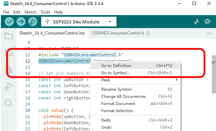
If you wish to learn more about USBHIDMouse, you can select it in the code, right-click, and choose “Go to Definition”.
36.3. Project USB Keypad Example
In this project, we plan to use the USB-OTG of the ESP32-S3 to emulate the keyboard functionality of a computer, allowing the ESP32-S3 to simulate keyboard input.
36.3.1. Component List
ESP32-S3 WROOM x1
|
GPIO Extension Board x1
|
||
Breadboard x1
|
|||
Push button x4
|
Resistor 10kΩ x4
|
Jumper M/M x5
|
|
36.3.1.1. Power
ESP32-S3 WROOM needs 5V power supply.
In this tutorial, we connect ESP32-S3 WROOM’s USB-UART to computer via USB cable to power and program it.
After uploading the code, you can also use other 5V power source to power it.
In the following projects, we only use USB cable to power ESP32-S3 WROOM by default.
In the whole tutorial, we don’t use DC jack on the T extension board to power ESP32-S3 WROOM, so 5V and 3.3V (including EXT 3.3V) on the extension board are provided by ESP32-S3 WROOM.
If power supply is connected to the DC jack of extension board to power ESP32-S3 WROOM, the extension board’s 5V and EXT 3.3V are provided by external power resource.
36.3.2. Circuit
Schematic diagram
|
Hardware connection. If you need any support, please feel free to contact us via: support@freenove.com
|
36.3.3. Sketch
36.3.3.1. Sketch_KeyboardControl
Compile and upload the code to the ESP32S3.
Important note: Upon the code finishes uploading, connect the USB cable to the USB-OTG interface.
When the four buttons on the breadboard are pressed, the ESP32-S3 emulates the pressing of the directional arrow keys on a computer keyboard.
When the onboard IO0 button is pressed, the ESP32-S3 emulates the pressing of the space bar on a computer keyboard.

The following is the program code:
1/*
2 KeyboardAndMouseControl
3
4 Hardware:
5 - five pushbuttons attached to D12, D13, D14, D15, D0
6
7 The mouse movement is always relative. This sketch reads four pushbuttons, and
8 uses them to set the movement of the mouse.
9
10 WARNING: When you use the Mouse.move() command, the Arduino takes over your
11 mouse! Make sure you have control before you use the mouse commands.
12
13 created 15 Mar 2012
14 modified 27 Mar 2012
15 by Tom Igoe
16
17 This example code is in the public domain.
18
19 http://www.arduino.cc/en/Tutorial/KeyboardAndMouseControl
20*/
21#define ARDUINO_USB_MODE 0
22#ifndef ARDUINO_USB_MODE
23#error This ESP32 SoC has no Native USB interface
24#elif ARDUINO_USB_MODE == 1
25#warning This sketch should be used when USB is in OTG mode
26void setup() {}
27void loop() {}
28#else
29
30#include "USB.h"
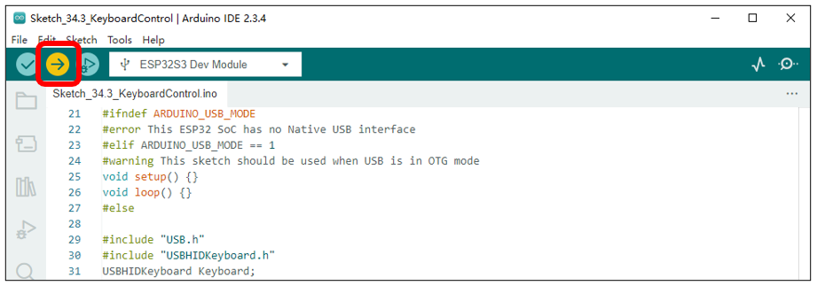
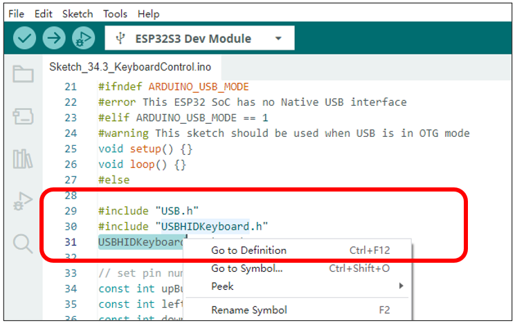
31#include "USBHIDKeyboard.h"
32USBHIDKeyboard Keyboard;
33
34// set pin numbers for the five buttons:
35const int upButton = 14;
36const int leftButton = 13;
37const int downButton = 12;
38const int rightButton = 11;
39const int mouseButton = 0;
40
41void setup() { // initialize the buttons' inputs:
42 pinMode(upButton, INPUT_PULLUP);
43 pinMode(downButton, INPUT_PULLUP);
44 pinMode(leftButton, INPUT_PULLUP);
45 pinMode(rightButton, INPUT_PULLUP);
46 pinMode(mouseButton, INPUT_PULLUP);
47
48 Keyboard.begin();
49 USB.begin();
50}
51
52void loop() {
53 // use the pushbuttons to control the keyboard:
54 if (digitalRead(upButton) == LOW) {
55 Keyboard.write(KEY_UP_ARROW);
56 }
57 if (digitalRead(downButton) == LOW) {
58 Keyboard.write(KEY_DOWN_ARROW);
59 }
60 if (digitalRead(leftButton) == LOW) {
61 Keyboard.write(KEY_LEFT_ARROW);
62 }
63 if (digitalRead(rightButton) == LOW) {
64 Keyboard.write(KEY_RIGHT_ARROW);
65 }
66 if (digitalRead(mouseButton) == LOW) {
67 Keyboard.write(KEY_SPACE);
68 }
69 delay(5);
70}
71#endif /* ARDUINO_USB_MODE */
Verify the configuration settings. If the configuration is incorrect, the program will not execute as expected. Please review the compilation prompts for details.
1#define ARDUINO_USB_MODE 0
2#ifndef ARDUINO_USB_MODE
3#error This ESP32 SoC has no Native USB interface
4#elif ARDUINO_USB_MODE == 1
5#warning This sketch should be used when USB is in OTG mode
6void setup() {}
7void loop() {}
8#else
Header files related to USB HID keyboard and the instantiation of a keyboard class object.
1#include "USB.h"
2#include "USBHIDKeyboard.h"
3USBHIDKeyboard Keyboard;
USB keyboard and USB driver initialization. Note that USB.begin() should be called last in the initialization sequence.
1Keyboard.begin();
2USB.begin();
Read the state of the buttons and, based on their status, have the ESP32-S3’s USB-OTG emulate the signals for pressing the directional keys and the space bar.
 1void loop() {
 2  // use the pushbuttons to control the keyboard:
 3  if (digitalRead(upButton) == LOW) {
 4    Keyboard.write(KEY_UP_ARROW);
 5  }
 6  if (digitalRead(downButton) == LOW) {
 7    Keyboard.write(KEY_DOWN_ARROW);
 8  }
 9  if (digitalRead(leftButton) == LOW) {
10    Keyboard.write(KEY_LEFT_ARROW);
11  }
12  if (digitalRead(rightButton) == LOW) {
13    Keyboard.write(KEY_RIGHT_ARROW);
14  }
15  if (digitalRead(mouseButton) == LOW) {
16    Keyboard.write(KEY_SPACE);
17  }
18  delay(5);
19}
If you wish to learn more about USBHIDKeyboard, you can select it in the code, right-click, and choose “Go to Definition”.
36.4. Project USB Control Device Example
In this project, we will use the USB-OTG feature of the ESP32-S3 to demonstrate how to control computer media volume, screen brightness, and other similar functions.
36.4.1. Component List
ESP32-S3 WROOM x1
|
GPIO Extension Board x1
|
||
Breadboard x1
|
|||
Push button x4
|
Resistor 10kΩ x4
|
Jumper M/M x5
|
|
36.4.1.1. Power
ESP32-S3 WROOM needs 5V power supply.
In this tutorial, we connect ESP32-S3 WROOM’s USB-UART to computer via USB cable to power and program it.
After uploading the code, you can also use other 5V power source to power it.
In the following projects, we only use USB cable to power ESP32-S3 WROOM by default.
In the whole tutorial, we don’t use DC jack on the T extension board to power ESP32-S3 WROOM, so 5V and 3.3V (including EXT 3.3V) on the extension board are provided by ESP32-S3 WROOM.
If power supply is connected to the DC jack of extension board to power ESP32-S3 WROOM, the extension board’s 5V and EXT 3.3V are provided by external power resource.
36.4.2. Circuit
Schematic diagram
|
Hardware connection. If you need any support, please feel free to contact us via: support@freenove.com
|
36.4.3. Sketch
36.4.3.1. Sketch_ConsumerControl
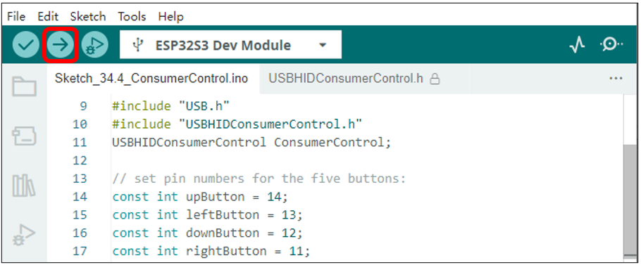
Important note: Upon the code finishes uploading, connect the USB cable to the USB-OTG interface.
When the up and down buttons on the breadboard are pressed, the ESP32-S3 controls the computer’s media volume to increase and decrease.
When the left and right buttons on the breadboard are pressed, the ESP32-S3 controls the computer’s screen brightness to increase and decrease.
The following is the program code:
 1#define ARDUINO_USB_MODE 0
 2#ifndef ARDUINO_USB_MODE
 3#error This ESP32 SoC has no Native USB interface
 4#elif ARDUINO_USB_MODE == 1
 5#warning This sketch should be used when USB is in OTG mode
 6void setup() {}
 7void loop() {}
 8#else
 9
10#include "USB.h"
11#include "USBHIDConsumerControl.h"
12USBHIDConsumerControl ConsumerControl;
13
14// set pin numbers for the five buttons:
15const int upButton = 14;
16const int leftButton = 13;
17const int downButton = 12;
18const int rightButton = 11;
19
20void setup() {
21  pinMode(upButton, INPUT_PULLUP);
22  pinMode(downButton, INPUT_PULLUP);
23  pinMode(leftButton, INPUT_PULLUP);
24  pinMode(rightButton, INPUT_PULLUP);
25
26  ConsumerControl.begin();
27  USB.begin();
28}
29
30void loop() {
31  // use the pushbuttons to control the keyboard:
32  if (digitalRead(upButton) == LOW) {
33    ConsumerControl.press(CONSUMER_CONTROL_VOLUME_INCREMENT);
34    ConsumerControl.release();
35  }
36  if (digitalRead(downButton) == LOW) {
37    ConsumerControl.press(CONSUMER_CONTROL_VOLUME_DECREMENT);
38    ConsumerControl.release();
39  }
40  if (digitalRead(leftButton) == LOW) {
41    ConsumerControl.press(CONSUMER_CONTROL_BRIGHTNESS_INCREMENT);
42    ConsumerControl.release();
43  }
44  if (digitalRead(rightButton) == LOW) {
45    ConsumerControl.press(CONSUMER_CONTROL_BRIGHTNESS_DECREMENT);
46    ConsumerControl.release();
47  }
48  delay(100);
49}
50#endif /* ARDUINO_USB_MODE */
Verify the configuration settings. If the configuration is incorrect, the program will not execute as expected. Please review the compilation prompts for details.
1#define ARDUINO_USB_MODE 0
2#ifndef ARDUINO_USB_MODE
3#error This ESP32 SoC has no Native USB interface
4#elif ARDUINO_USB_MODE == 1
5#warning This sketch should be used when USB is in OTG mode
6void setup() {}
7void loop() {}
8#else
Header files related to USB device control and the instantiation of a device control class object.
1#include "USBHIDConsumerControl.h"
2USBHIDConsumerControl ConsumerControl;
USB device control class driver initialization, USB driver initialization. Note that USB.begin() should be called last in the initialization sequence.
1ConsumerControl.begin();
2USB.begin();
Read the state of the buttons. If the up or down buttons are pressed, control the volume of the computer’s media. If the left or right buttons are pressed, control the change in screen brightness.
 1void loop() {
 2  // use the pushbuttons to control the keyboard:
 3  if (digitalRead(upButton) == LOW) {
 4    ConsumerControl.press(CONSUMER_CONTROL_VOLUME_INCREMENT);
 5    ConsumerControl.release();
 6  }
 7  if (digitalRead(downButton) == LOW) {
 8    ConsumerControl.press(CONSUMER_CONTROL_VOLUME_DECREMENT);
 9    ConsumerControl.release();
10  }
11  if (digitalRead(leftButton) == LOW) {
12    ConsumerControl.press(CONSUMER_CONTROL_BRIGHTNESS_INCREMENT);
13    ConsumerControl.release();
14  }
15  if (digitalRead(rightButton) == LOW) {
16    ConsumerControl.press(CONSUMER_CONTROL_BRIGHTNESS_DECREMENT);
17    ConsumerControl.release();
18  }
19  delay(100);
20}
If you wish to learn more about USBHIDKeyboard, you can select it in the code, right-click, and choose “Go to Definition”.