26. Chapter Camera Tcp Server
In the previous section, we used web page to display the video data captured by ESP32-S3, and in this section, we will use a mobile phone to display it.
26.1. Project Camera Tcp Server
Connect ESP32-S3 using USB and check its IP address through serial monitor. Use a mobile phone to obtain video and image data.
26.1.1. Component List
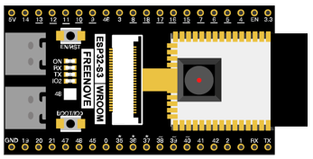
ESP32-S3 WROOM x1
|
USB cable x1
|

26.1.2. Install Freenove app
There are three ways to install app, you can choose any one.
26.1.2.1. Method 1
Use Google play to search “Freenove”, download and install.
26.1.2.2. Method 2
Visit https://play.google.com/store/apps/details?id=com.freenove.suhayl.Freenove, and click install.
26.1.2.3. Method 3
Visit https://github.com/Freenove/Freenove_app_for_Android, download the files in this library, and install freenove.apk to your Android phone manually.
26.1.2.4. Menu
Open application “Freenove”, as shown below:
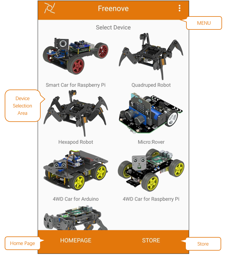
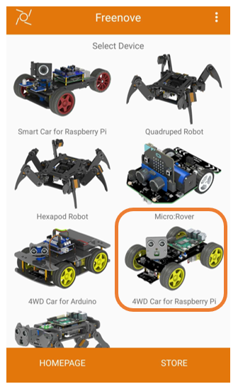
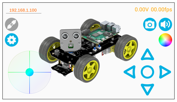
26.1.2.5. Freenove 4WD Car for Raspberry Pi
In this chapter, we use Freenove 4WD Car for Raspberry Pi, so it is necessary to understand the interface of this mode.
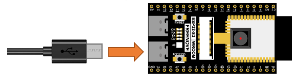
26.1.3. Circuit
Connect Freenove ESP32-S3 to the computer using the USB cable.
26.1.4. Sketch
After making sure the Tools is configured correctly, don’t run Sketch. Due to WiFi, we need to modify Sketch a little bit based on physical situation.
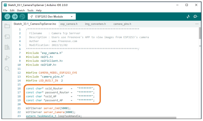
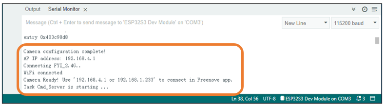
In the box in the figure above, ssid_Router and password_Router are the user’s Router name and password, which need to be modified according to the actual name and password. ssid_AP and password_AP are name and password of a AP created by ESP32-S3, and they are freely set by the user. When all settings are correct, compile and upload the code to ESP32-S3, turn on the serial port monitor, and set the baud rate to 115200. The serial monitor will print out two IP addresses.
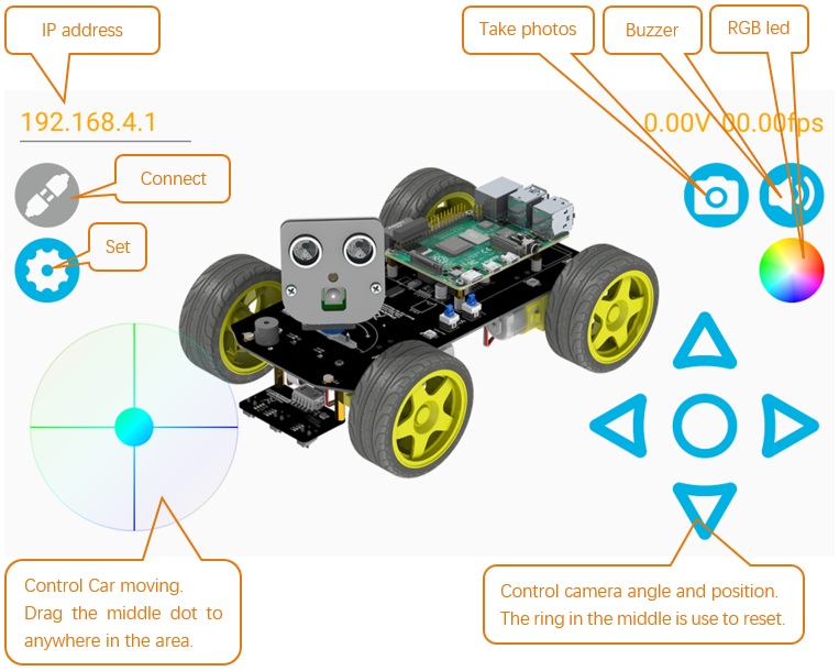
There are two methods for you to check camera data of ESP32-S3 via mobile phone APP.
26.1.4.1. Method 1:
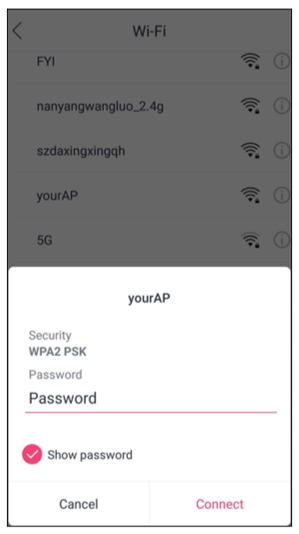
Using your phone’s WiFi function, select the WiFi name represented by ssid_AP in Sketch and enter the password “password_AP” to connect.
Next, open Freenove app and select 4WD Car for Raspberry Pi mode.
Enter the IP address printed by serial port in the new interface, which generally is “192.168.4.1”
Click “Connect”.
26.1.4.2. Method 2:
Using your phone’s WiFi function, select the router named ssid_Router and enter the password “ssid_password” to connect. And then open Freenove app and select 4WD Car for Raspberry Pi mode. The operation is similar to Method 1.
Enter the IP address printed by serial port in the new interface, which generally is not “192.168.4.1” but another one. The IP address in this example is “192.168.1.100”. After entering the IP address, click “Connect”.
The following is the main program code. You need include other code files in the same folder when write your own code.
26.1.4.3. Sketch_Camera_Tcp_Server
  1/**********************************************************************
  2  Filename    : Camera Tcp Serrver
  3  Description : Users use Freenove's APP to view images from ESP32S3's camera
  4  Auther      : www.freenove.com
  5  Modification: 2026/05/16
  6**********************************************************************/
  7#include "esp_camera.h"
  8#include <WiFi.h>
  9#include <WiFiClient.h>
 10#include <WiFiAP.h>
 11
 12#define CAMERA_MODEL_ESP32S3_EYE
 13#include "camera_pins.h"
 14#define LED_BUILT_IN  2
 15
 16const char* ssid_Router     =   "********";
 17const char* password_Router =   "********";
 18const char *ssid_AP         =   "********";
 19const char *password_AP     =   "********";
 20
 21WiFiServer server_Cmd(5000);
 22WiFiServer server_Camera(8000);
 23extern TaskHandle_t loopTaskHandle;
 24camera_config_t config;
 25void camera_init();
 26
 27void setup() {
 28  Serial.begin(115200);
 29  Serial.setDebugOutput(false);
 30  Serial.println();
 31  pinMode(LED_BUILT_IN, OUTPUT);
 32
 33  camera_init();
 34
 35  WiFi.softAP(ssid_AP, password_AP);
 36  IPAddress myIP = WiFi.softAPIP();
 37  Serial.print("AP IP address: ");
 38  Serial.println(myIP);
 39  server_Camera.begin(8000);
 40  server_Cmd.begin(5000);
 41  /////////////////////////////////////////////////////
 42  WiFi.begin(ssid_Router, password_Router);
 43  Serial.print("Connecting ");
 44  Serial.print(ssid_Router);
 45  while (WiFi.status() != WL_CONNECTED) {
 46    delay(500);
 47    Serial.print(".");
 48  }
 49  while (WiFi.STA.hasIP() != true) {
 50    Serial.print(".");
 51    delay(500);
 52  }
 53  Serial.println("");
 54  Serial.println("WiFi connected");
 55  /////////////////////////////////////////////////////
 56  Serial.print("Camera Ready! Use '");
 57  Serial.print(WiFi.softAPIP());
 58  Serial.print(" or ");
 59  Serial.print(WiFi.localIP());
 60  Serial.println("' to connect in Freenove app.");
 61
 62  disableCore0WDT();
 63  xTaskCreateUniversal(loopTask_Cmd, "loopTask_Cmd", 8192, NULL, 1, &loopTaskHandle, 0);		//loopTask_Cmd uses core 0.
 64  xTaskCreateUniversal(loopTask_Blink, "loopTask_Blink", 8192, NULL, 1, &loopTaskHandle, 0);//loopTask_Blink uses core 0.
 65}
 66//task loop uses core 1.
 67void loop() {
 68  WiFiClient client = server_Camera.accept();           // listen for incoming clients
 69  if (client) {                                            // if you get a client,
 70    Serial.println("Camera Server connected to a client.");// print a message out the serial port
 71    String currentLine = "";                               // make a String to hold incoming data from the client
 72    while (client.connected()) {                           // loop while the client's connected
 73      camera_fb_t * fb = NULL;
 74      size_t jpg_buf_len = 0;
 75      uint8_t *jpg_buf = NULL;
 76      while (client.connected()) {
 77        fb = esp_camera_fb_get();
 78        if (!fb){
 79            Serial.println("Camera capture failed");
 80        }
 81        else{
 82            if (fb->format != PIXFORMAT_JPEG){
 83                bool jpeg_converted = frame2jpg(fb, 80, &jpg_buf, &jpg_buf_len);
 84                esp_camera_fb_return(fb);
 85                fb = NULL;
 86                if (!jpeg_converted){
 87                    Serial.println("JPEG compression failed");
 88                    continue;
 89                }
 90            }
 91            else{
 92                jpg_buf_len = fb->len;
 93                jpg_buf = fb->buf;
 94            }
 95            uint8_t slen[4];
 96            slen[0] = jpg_buf_len >> 0;
 97            slen[1] = jpg_buf_len >> 8;
 98            slen[2] = jpg_buf_len >> 16;
 99            slen[3] = jpg_buf_len >> 24;
100            client.write(slen, 4);
101            client.write(jpg_buf, jpg_buf_len);
102        }
103        if (fb){
104            esp_camera_fb_return(fb);
105            fb = NULL;
106            jpg_buf = NULL;
107        }
108        else if (jpg_buf){
109            free(jpg_buf);
110            jpg_buf = NULL;
111        }
112      }
113    }
114    // close the connection:
115    client.stop();
116    Serial.println("Camera Client Disconnected.");
117  }
118}
119
120void loopTask_Cmd(void *pvParameters) {
121  Serial.println("Task Cmd_Server is starting ... ");
122  while (1) {
123    WiFiClient client = server_Cmd.accept(); // listen for incoming clients
124    if (client) {                               // if you get a client,
125      Serial.println("Command Server connected to a client.");// print a message out the serial port
126      String currentLine = "";                 // make a String to hold incoming data from the client
127      while (client.connected()) {             // loop while the client's connected
128        if (client.available()) {              // if there's bytes to read from the client,
129          char c = client.read();              // read a byte, then
130          client.write(c);
131          Serial.write(c);                     // print it out the serial monitor
132          if (c == '\n') {                     // if the byte is a newline character
133            currentLine = "";
134          }
135          else {
136            currentLine += c;                  // add it to the end of the currentLine
137          }
138        }
139      }
140      // close the connection:
141      client.stop();
142      Serial.println("Command Client Disconnected.");
143    }
144  }
145}
146void loopTask_Blink(void *pvParameters) {
147  Serial.println("Task Blink is starting ... ");
148  while (1) {
149    digitalWrite(LED_BUILT_IN, !digitalRead(LED_BUILT_IN));
150    delay(1000);
151  }
152}
153
154void camera_init() {
155  config.ledc_channel = LEDC_CHANNEL_0;
156  config.ledc_timer = LEDC_TIMER_0;
157  config.pin_d0 = Y2_GPIO_NUM;
158  config.pin_d1 = Y3_GPIO_NUM;
159  config.pin_d2 = Y4_GPIO_NUM;
160  config.pin_d3 = Y5_GPIO_NUM;
161  config.pin_d4 = Y6_GPIO_NUM;
162  config.pin_d5 = Y7_GPIO_NUM;
163  config.pin_d6 = Y8_GPIO_NUM;
164  config.pin_d7 = Y9_GPIO_NUM;
165  config.pin_xclk = XCLK_GPIO_NUM;
166  config.pin_pclk = PCLK_GPIO_NUM;
167  config.pin_vsync = VSYNC_GPIO_NUM;
168  config.pin_href = HREF_GPIO_NUM;
169  config.pin_sccb_sda = SIOD_GPIO_NUM;
170  config.pin_sccb_scl = SIOC_GPIO_NUM;
171  config.pin_pwdn = PWDN_GPIO_NUM;
172  config.pin_reset = RESET_GPIO_NUM;
173  config.xclk_freq_hz = 10000000;
174  config.frame_size = FRAMESIZE_QVGA;
175  config.pixel_format = PIXFORMAT_JPEG; // for streaming
176  config.grab_mode = CAMERA_GRAB_WHEN_EMPTY;
177  config.fb_location = CAMERA_FB_IN_PSRAM;
178  config.jpeg_quality = 10;
179  config.fb_count = 1;
180
181  // camera init
182  esp_err_t err = esp_camera_init(&config);
183  if (err != ESP_OK) {
184    if(err==ESP_ERR_NOT_SUPPORTED){
185      config.pixel_format = PIXFORMAT_RGB565;
186      esp_err_t err = esp_camera_init(&config);
187      if (err != ESP_OK) {
188        Serial.printf("Camera init failed with error 0x%x", err);
189        return;
190      }
191    }
192  }
193
194  sensor_t * s = esp_camera_sensor_get();
195  // drop down frame size for higher initial frame rate
196  uint16_t pid = s->id.PID;
197  if(pid == OV2640_PID){
198    s->set_hmirror(s, 1);
199    s->set_vflip(s, 1);
200  }
201  else if(pid == OV3660_PID){
202    s->set_hmirror(s, 1);
203    s->set_vflip(s, 0);
204  }
205  else if(pid == GC2145_PID){
206    s->set_hmirror(s, 0);
207    delay(500);
208    s->set_vflip(s, 0);
209  }
210  else if(pid == GC0308_PID){
211    s->set_hmirror(s, 0);
212    delay(500);
213    s->set_vflip(s, 0);
214  }
215  else{
216    s->set_hmirror(s, 1);
217    s->set_vflip(s, 0);
218  }
219  s->set_brightness(s, 1);  // Slightly increase brightness
220  s->set_saturation(s, 0);  // Reduce saturation
221  s->set_ae_level(s, -3);   // Set exposure compensation level
222}
Include header files that drive camera and WiFi.
1#include "esp_camera.h"
2#include <WiFi.h>
3#include <WiFiClient.h>
4#include <WiFiAP.h>
5
6#define CAMERA_MODEL_ESP32S3_EYE
7#include "camera_pins.h"
Set name and password for router that ESP32-S3 needs to connect to. And set ESP32-S3 to open two servers, whose port are 8000 and 5000 respectively.
1const char* ssid_Router     =   "********";
2const char* password_Router =   "********";
3const char *ssid_AP         =   "********";
4const char *password_AP     =   "********";
Enable ESP32-S3’s server function and set two monitor ports as 5000 and 8000. In general, the two port numbers do not require modifications.
1WiFiServer server_Cmd(5000);
2WiFiServer server_Camera(8000);
3extern TaskHandle_t loopTaskHandle;
Initialize serial port, set baud rate to 115200; open the debug and output function of the serial.
1
2void setup() {
3  Serial.begin(115200);
Define a variable for camera interface and initialize it.
 1        if (client.available()) {              // if there's bytes to read from the client,
 2          char c = client.read();              // read a byte, then
 3          client.write(c);
 4          Serial.write(c);                     // print it out the serial monitor
 5          if (c == '\n') {                     // if the byte is a newline character
 6            currentLine = "";
 7          }
 8          else {
 9            currentLine += c;                  // add it to the end of the currentLine
10          }
11        }
12      }
13      // close the connection:
14      client.stop();
15      Serial.println("Command Client Disconnected.");
16    }
17  }
18}
19void loopTask_Blink(void *pvParameters) {
20  Serial.println("Task Blink is starting ... ");
21  while (1) {
22    digitalWrite(LED_BUILT_IN, !digitalRead(LED_BUILT_IN));
23    delay(1000);
24  }
25}
26
27void camera_init() {
28  config.ledc_channel = LEDC_CHANNEL_0;
29  config.ledc_timer = LEDC_TIMER_0;
30  config.pin_d0 = Y2_GPIO_NUM;
31  config.pin_d1 = Y3_GPIO_NUM;
32  config.pin_d2 = Y4_GPIO_NUM;
33  config.pin_d3 = Y5_GPIO_NUM;
34  config.pin_d4 = Y6_GPIO_NUM;
35  config.pin_d5 = Y7_GPIO_NUM;
36  config.pin_d6 = Y8_GPIO_NUM;
37  config.pin_d7 = Y9_GPIO_NUM;
38  config.pin_xclk = XCLK_GPIO_NUM;
39  config.pin_pclk = PCLK_GPIO_NUM;
40  config.pin_vsync = VSYNC_GPIO_NUM;
41  config.pin_href = HREF_GPIO_NUM;
42  config.pin_sccb_sda = SIOD_GPIO_NUM;
43  config.pin_sccb_scl = SIOC_GPIO_NUM;
44  config.pin_pwdn = PWDN_GPIO_NUM;
45  config.pin_reset = RESET_GPIO_NUM;
46  config.xclk_freq_hz = 10000000;
47  config.frame_size = FRAMESIZE_QVGA;
48  config.pixel_format = PIXFORMAT_JPEG; // for streaming
49  config.grab_mode = CAMERA_GRAB_WHEN_EMPTY;
50  config.fb_location = CAMERA_FB_IN_PSRAM;
51  config.jpeg_quality = 10;
52  config.fb_count = 1;
53
54  // camera init
55  esp_err_t err = esp_camera_init(&config);
Loop function will constantly send camera data obtained to mobile phone APP.
 1String currentLine = "";                               // make a String to hold incoming data from the client
 2while (client.connected()) {                           // loop while the client's connected
 3  camera_fb_t * fb = NULL;
 4  size_t jpg_buf_len = 0;
 5  uint8_t *jpg_buf = NULL;
 6  while (client.connected()) {
 7    fb = esp_camera_fb_get();
 8    if (!fb){
 9        Serial.println("Camera capture failed");
10    }
11    else{
12        if (fb->format != PIXFORMAT_JPEG){
13            bool jpeg_converted = frame2jpg(fb, 80, &jpg_buf, &jpg_buf_len);
14            esp_camera_fb_return(fb);
15            fb = NULL;
16            if (!jpeg_converted){
The loopTask_Cmd() function sends the received instruction back to the phone app and prints it out through a serial port.
 1            }
 2            uint8_t slen[4];
 3            slen[0] = jpg_buf_len >> 0;
 4            slen[1] = jpg_buf_len >> 8;
 5            slen[2] = jpg_buf_len >> 16;
 6            slen[3] = jpg_buf_len >> 24;
 7            client.write(slen, 4);
 8            client.write(jpg_buf, jpg_buf_len);
 9        }
10        if (fb){
11            esp_camera_fb_return(fb);
12            fb = NULL;
13            jpg_buf = NULL;
14        }
15        else if (jpg_buf){
16            free(jpg_buf);
17            jpg_buf = NULL;
18        }
19      }
20    }
21    // close the connection:
22    client.stop();
23    Serial.println("Camera Client Disconnected.");
24  }
25}
26
loopTask_ Blink()function will control the blinking of LED. When you see LED blinking, it indicates that ESP32-S3 has been configured and starts working.
1void loopTask_Cmd(void *pvParameters) {
2  Serial.println("Task Cmd_Server is starting ... ");
3  while (1) {
4    WiFiClient client = server_Cmd.accept(); // listen for incoming clients
5    if (client) {                               // if you get a client,
6      Serial.println("Command Server connected to a client.");// print a message out the serial port
7      String currentLine = "";                 // make a String to hold incoming data from the client
If you do not have a router near you, or if you are outdoors, you can annotate the following code, and then compile and upload it to ESP32-S3. And you can display the video images on your phone by Method 1.
 1Serial.println(myIP);
 2server_Camera.begin(8000);
 3server_Cmd.begin(5000);
 4/////////////////////////////////////////////////////
 5WiFi.begin(ssid_Router, password_Router);
 6Serial.print("Connecting ");
 7Serial.print(ssid_Router);
 8while (WiFi.status() != WL_CONNECTED) {
 9  delay(500);
10  Serial.print(".");
11}
12while (WiFi.STA.hasIP() != true) {
13  Serial.print(".");
14  delay(500);
15}