Chapter 02 Button
The Boot button on the Freenove ESP32-S3 Display can be configured as a regular input button after the program starts.
Project 2.1 Button
Related Knowledge
Button
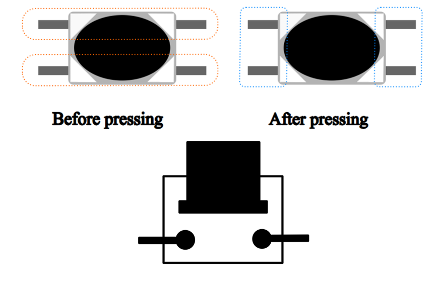
In embedded systems, buttons are one of the most common human-machine input devices. When a button is not pressed, its opposing contacts are connected while adjacent contacts remain disconnected. Conversely, when the button is pressed, adjacent contacts connect while opposing contacts disconnect.
Usage of the Boot Button on the Freenove ESP32-S3 Display:
Manual Entry into Download Mode:
When the board is powered on or reset, pressing and holding the Boot button forces the board into download mode.
In this mode, users can upload programs to the board via the serial port.
Use as a Regular Input Button:
If the Boot button is not pressed during power-on or reset, the board enters normal operation mode.
Once in operation mode, the Boot button can function as GPIO0, typically configured as a standard input button for user interaction.
Pull-up Resistor
The primary function of a pull-up resistor is to ensure that the button maintains a stable high-level state when not pressed, preventing false triggering caused by floating pins or signal noise. The pull-up resistor is connected between the GPIO pin and VCC.
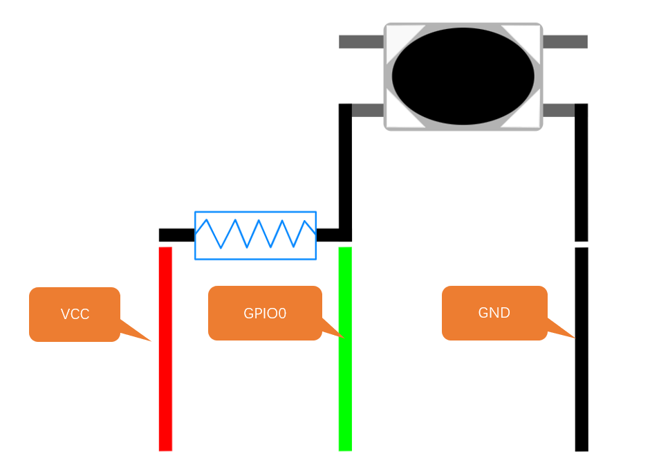
When the button is not pressed, Vcc is connected to GPIO0 through the resistor, resulting in a high-level signal at this pin.
When the button is pressed, GPIO0 is connected to GND, resulting in a low-level signal.
Therefore, by reading the GPIO0 pin state, we can determine whether the button is pressed or not.
How Interrupts Work
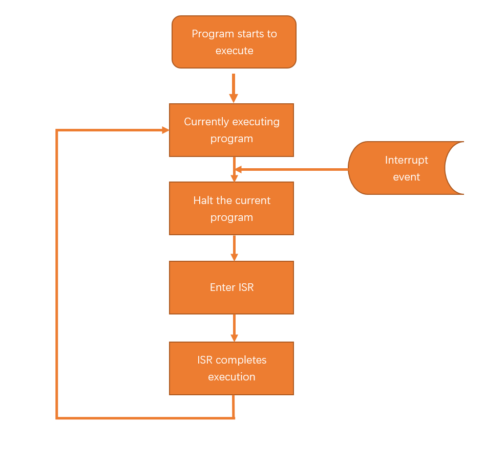
When an interrupt event is triggered, the Freenove ESP32-S3 Display receives an interrupt signal. At this moment, the Freenove ESP32-S3 Display pauses the currently executing program and instead executes the Interrupt Service Routine (ISR). The ISR contains the code that needs to be processed after the interrupt event occurs. Once the ISR execution is complete, the Freenove ESP32-S3 Display will return to the state it was in before the interrupt occurred and continue executing the paused program, as shown in the diagram below.
Component List
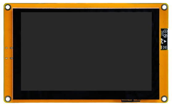
Freenove ESP32-S3 Display x 1
|
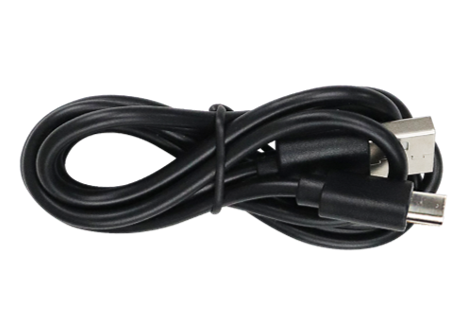
USB cable x1
|
Circuit
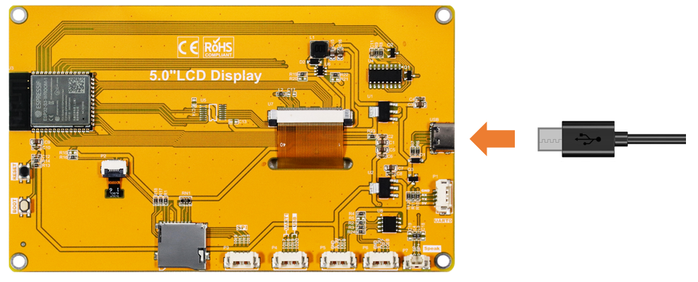
Connect Freenove ESP32-S3 Display to the computer with USB cable.
Sketch
Open “Sketch_02.1_Button” folder under “Freenove_ESP32_S3_Display_FNK0115\Sketches” and double-click “Sketch_02.1_Button.ino”.
Code Explanation
Define the button pin:
1#define BUTTON_PIN 0
Button initialization function, which sets the pin to input pull-up mode and configures the interrupt to trigger on a falling edge:
1// Button initialization function
2void buttonInit(void) {
3  pinMode(BUTTON_PIN, INPUT_PULLUP);
4  attachInterrupt(digitalPinToInterrupt(BUTTON_PIN), handleInterrupt, FALLING);
5}
External interrupt function, which is used for button debounce:
 1void IRAM_ATTR handleInterrupt() {
 2  static unsigned long last_interrupt_time = 0;
 3  unsigned long interrupt_time = millis();
 4
 5  // If the interval between two interrupts exceeds 80ms, it is considered a valid key press.
 6  if (interrupt_time - last_interrupt_time > 80) {
 7    interruptCounter++;
 8  }
 9  last_interrupt_time = interrupt_time;
10}
Click “Upload” to upload the code to Freenove_ESP32_S3_Display.
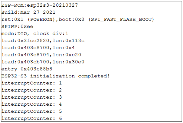
When the button is pressed, the Serial Monitor will print the total number of button presses.
Please note: This chapter does not involve the use of the screen. After the code for this chapter, the screen may not light up, which is normal and not a hardware malfunction. If you need to verify whether the screen is functioning properly, please refer to Chapter 10 for testing.