5. Chapter RGB LED
In this chapter, we will learn how to control a RGB LED.
An RGB LED has 3 LEDs integrated into one LED component. It can respectively emit Red, Green and Blue light. In order to do this, it requires 4 pins (this is also how you identify it). The long pin (1) is the common which is the Anode (+) or positive lead, the other 3 are the Cathodes (-) or negative leads. A rendering of a RGB LED and its electronic symbol are shown below. We can make RGB LED emit various colors of light and brightness by controlling the 3 Cathodes (2, 3 & 4) of the RGB LED
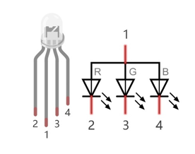
Red, Green, and Blue light are called 3 Primary Colors when discussing light (Note: for pigments such as paints, the 3 Primary Colors are Red, Blue and Yellow). When you combine these three Primary Colors of light with varied brightness, they can produce almost any color of visible light. Computer screens, single pixels of cell phone screens, neon lamps, etc. can all produce millions of colors due to phenomenon.

RGB
If we use a three 8 bit PWM to control the RGB LED, in theory, we can create 28*28*28=16777216 (16 million) colors through different combinations of RGB light brightness.
Next, we will use RGB LED to make a multicolored LED.
5.1. Project Multicolored LED
5.1.1. Component List
Raspberry Pi (with 40 GPIO) x1 GPIO Extension Board & Ribbon Cable x1 Breadboard x1 |
RGB LED
|
Jumper Wire
|
Resistor 220Ω x3
|


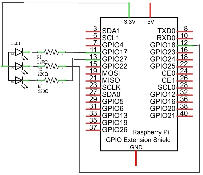
5.1.2. Circuit
Schematic diagram
|
Hardware connection. If you need any support,please feel free to contact us via:
|
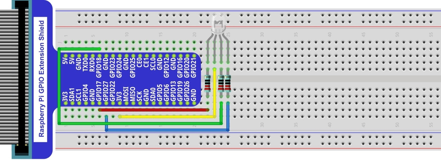
Note
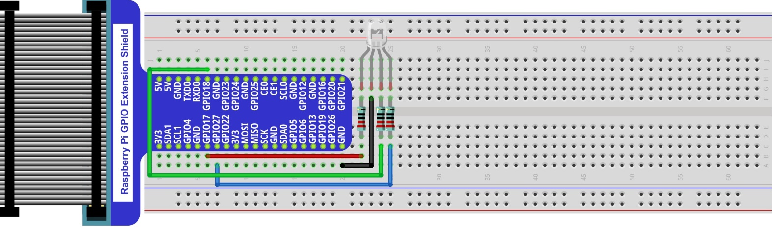
In this kit, the RGB led is Common anode. The voltage difference between LED will make it work. There is no visible GND. The GPIO ports can also receive current while in output mode.If circuit above doesn’t work, the RGB LED may be common cathode. Please try following wiring.There is no need to modify code for random color.
If circuit above doesn’t work, the RGB LED may be common cathode. Please try following wiring.
There is no need to modify code for random color.
5.1.3. Code
We need to use RGBLED class to control RGBLED. The parameters for setting the RGBLED as common cathode or common anode are provided in the RGBLED class. You can set it according to the type of your RGB LED, and the default setting in our example code is based on common anode.
5.1.3.1. Python Code ColorfulLED
First, observe the project result, and then learn about the code in detail.
Hint
If you have any concerns, please contact us via: support@freenove.com
Use cd command to enter 05.1.1_ColorfulLED directory of Python code.
$ cd ~/Freenove_Kit/Code/Python_GPIOZero_Code/05.1.1_ColorfulLED
Use python command to execute python code “ColorfulLED.py”.
$ python ColorfulLED.py
After the program is executed, you will see that the RGB LED randomly lights up different colors.
The following is the program code:
 1#!/usr/bin/env python3
 2########################################################################
 3# Filename    : ColorfulLED.py
 4# Description : Random color change ColorfulLED
 5# Author      : www.freenove.com
 6# modification: 2023/05/11
 7########################################################################
 8from gpiozero import RGBLED
 9import time
10import random
11
12#led = RGBLED(red="J8:11", green="J8:12", blue="J8:13", active_high=False) # define the pins for R:11,G:12,B:13
13led = RGBLED(red=17, green=18, blue=27, active_high=False) # define the pins for R:GPIO17,G:GPIO18,B:GPIO27
14# If your RGBLED is a common cathode LED, set active_high to True
15
16def setColor(r_val,g_val,b_val):      # change duty cycle for three pins to r_val,g_val,b_val
17    led.red=r_val/100                 # change pwmRed duty cycle to r_val
18    led.green = g_val/100             # change pwmRed duty cycle to r_val
19    led.blue = b_val/100              # change pwmRed duty cycle to r_val
20
21def loop():
22    while True :
23        r=random.randint(0,100)  #get a random in (0,100)
24        g=random.randint(0,100)
25        b=random.randint(0,100)
26        setColor(r,g,b)          #set random as a duty cycle value
27        print ('r=%d, g=%d, b=%d ' %(r ,g, b))
28        time.sleep(1)
29
30def destroy():
31    led.close()
32
33if __name__ == '__main__':     # Program entrance
34    print ('Program is starting ... ')
35    try:
36        loop()
37    except KeyboardInterrupt:  # Press ctrl-c to end the program.
38        destroy()
39        print("Ending program")
Import the RGBLED class that controls RGBLED from the gpiozero library.
1from gpiozero import RGBLED
Create the RGBLED class for controlling the RGBLED.
1led = RGBLED(red=17, green=18, blue=27, active_high=False) # define the pins for R:GPIO17,G:GPIO18,B:GPIO2
In the previous chapter, we learned how to make a pin output PWM using the Python language. In this project, we output to three pins via PWM. In the “while” loop of the “loop” function, we first generate three random numbers and then assign these three random numbers to the PWM values of the three pins, which will make the RGB LED randomly produce multiple colors.
1def loop():
2    while True :
3        r=random.randint(0,100)  #get a random in (0,100)
4        g=random.randint(0,100)
5        b=random.randint(0,100)
6        setColor(r,g,b)          #set random as a duty cycle value
7        print ('r=%d, g=%d, b=%d ' %(r ,g, b))
8        time.sleep(1)
For more information about the methods used by the RGBLED class in the GPIO Zero library,please refer to: https://gpiozero.readthedocs.io/en/stable/api_output.html#rgbled