11. Chapter Thermistor
In this chapter, we will learn about Thermistors which are another kind of Resistor.
11.1. Project Thermometer
A Thermistor is a type of Resistor whose resistance value is dependent on temperature and changes in temperature. Therefore, we can take advantage of this characteristic to make a Thermometer.
11.1.1. Component List
|
|
Thermistor x1
|
|
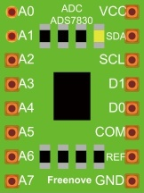
ADC module x1
|
|
Jumper Wire M/M x14 |
|


11.1.2. Component knowledge
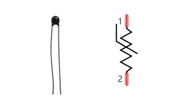
11.1.2.1. Thermistor
Thermistor is a temperature sensitive resistor. When it senses a change in temperature, the resistance of the Thermistor will change. We can take advantage of this characteristic by using a Thermistor to detect temperature intensity. A Thermistor and its electronic symbol are shown below.
The relationship between resistance value and temperature of a thermistor is:
- Where:
Rt is the thermistor resistance under T2 temperature;
R is in the nominal resistance of thermistor under T1 temperature;
EXP[n] is nth power of e;
B is for thermal index;
T1, T2 is Kelvin temperature (absolute temperature). Kelvin temperature=273.15 + Celsius temperature.
For the parameters of the Thermistor, we use: B=3950, R=10k, T1=25.
The circuit connection method of the Thermistor is similar to photoresistor, as the following:
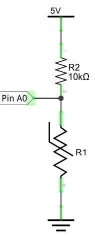
We can use the value measured by the ADC converter to obtain the resistance value of Thermistor, and then we can use the formula to obtain the temperature value.
Therefore, the temperature formula can be derived as:
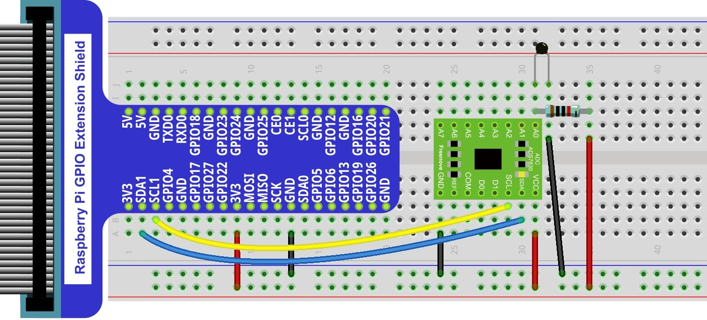
11.1.3. Circuit with ADS7830
The circuit of this project is similar to the one in last chapter. The only difference is that the Photoresistor is replaced by the Thermistor.
Schematic diagram
|
Hardware connection. If you need any support,please feel free to contact us via:
|
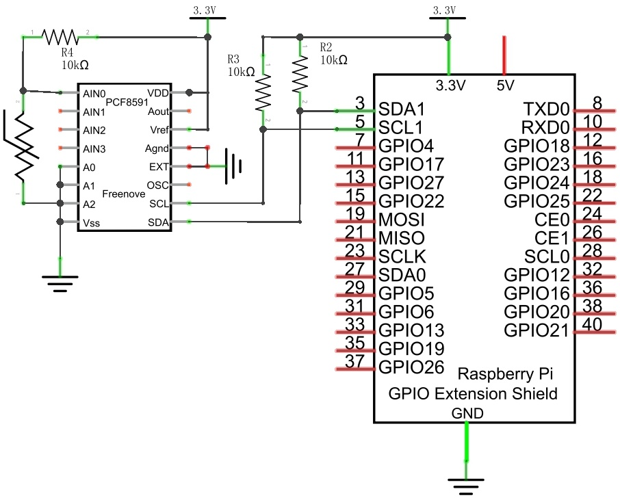
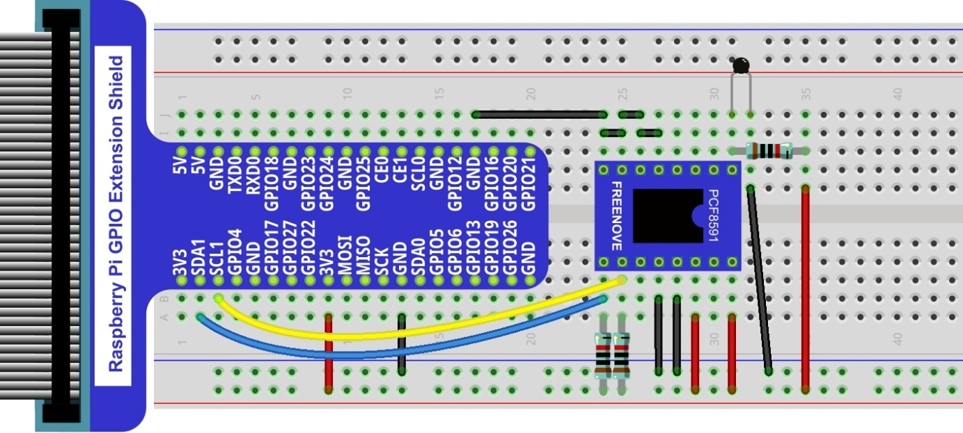
11.1.4. Circuit with PCF8591
The circuit of this project is similar to the one in the last chapter. The only difference is that the Photoresistor is replaced by the Thermistor.
Schematic diagram
|
Hardware connection. If you need any support,please feel free to contact us via:
|
11.1.5. Code
In this project code, the ADC value still needs to be read, but the difference here is that a specific formula is used to calculate the temperature value.
11.1.5.1. Python Code Thermometer
If you did not configure I2C, please refer to Chapter 7. If you did, please continue.
First, observe the project result, and then learn about the code in detail.
Hint
If you have any concerns, please contact us via: support@freenove.com
Use cd command to enter 11.1.1_Thermometer directory of Python code.
$ cd ~/Freenove_Kit/Code/Python_GPIOZero_Code/11.1.1_Thermometer
Use python command to execute Python code “Thermometer.py”.
$ python Thermometer.py
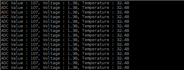
After the program is executed, the Terminal window will display the current ADC value, voltage value and temperature value. Try to “pinch” the thermistor (without touching the leads) with your index finger and thumb for a brief time, you should see that the temperature value increases.
The following is the code:
 1#!/usr/bin/env python3
 2#############################################################################
 3# Filename    : Thermometer.py
 4# Description : DIY Thermometer
 5# Author      : www.freenove.com
 6# modification: 2023/05/11
 7########################################################################
 8import time
 9import math
10from ADCDevice import *
11
12adc = ADCDevice() # Define an ADCDevice class object
13
14def setup():
15    global adc
16    if(adc.detectI2C(0x48)): # Detect the pcf8591.
17        adc = PCF8591()
18    elif(adc.detectI2C(0x4b)): # Detect the ads7830
19        adc = ADS7830()
20    else:
21        print("No correct I2C address found, \n"
22        "Please use command 'i2cdetect -y 1' to check the I2C address! \n"
23        "Program Exit. \n");
24        exit(-1)
25
26def loop():
27    while True:
28        value = adc.analogRead(0)        # read ADC value A0 pin
29        voltage = value / 255.0 * 3.3        # calculate voltage
30        Rt = 10 * voltage / (3.3 - voltage)    # calculate resistance value of thermistor
31        tempK = 1/(1/(273.15 + 25) + math.log(Rt/10)/3950.0) # calculate temperature (Kelvin)
32        tempC = tempK -273.15        # calculate temperature (Celsius)
33        print ('ADC Value : %d, Voltage : %.2f, Temperature : %.2f'%(value,voltage,tempC))
34        time.sleep(0.01)
35
36def destroy():
37    adc.close()
38
39if __name__ == '__main__':  # Program entrance
40    print ('Program is starting ... ')
41    setup()
42    try:
43        loop()
44    except KeyboardInterrupt: # Press ctrl-c to end the program.
45        destroy()
46        print("Ending program")
In the code, the ADC value of ADC module A0 port is read, and then calculates the voltage and the resistance of Thermistor according to Ohms Law. Finally, it calculates the temperature sensed by the Thermistor, according to the formula.