Chapter 1 LED
This chapter is the Start Point in the journey to build and explore ESP8266 electronic projects. We will start with simple “Blink” project.
Project 1.1 Blink
In this project, we will use ESP8266 to control blinking a common LED.
Component List
ESP8266 x1
|
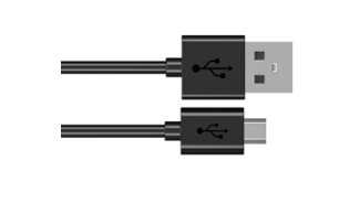
USB cable
|
||
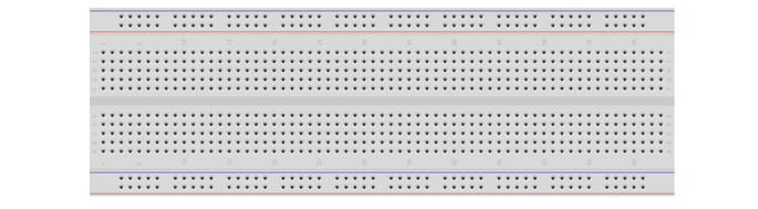
Breadboard x1
|
|||
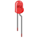
LED x1
|
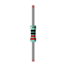
Resistor 220Ω x1
|
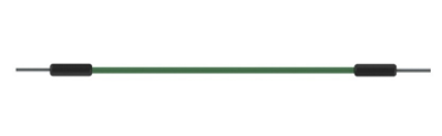
Jumper wire M/M x3
|
|

Component knowledge
LED
A LED is a type of diode. All diodes only work if current is flowing in the correct direction and have two poles. A LED will only work (light up) if the longer pin (+) of LED is connected to the positive output from a power source and the shorter pin is connected to the negative (-). Negative output is also referred to as Ground (GND). This type of component is known as “diodes” (think One-Way Street).
All common 2 lead diodes are the same in this respect. Diodes work only if the voltage of its positive electrode is higher than its negative electrode and there is a narrow range of operating voltage for most all common diodes of 1.9 and 3.4V. If you use much more than 3.3V the LED will be damaged and burn out.
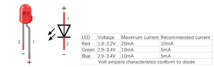
Note
LEDs cannot be directly connected to a power supply, which usually ends in a damaged component. A resistor with a specified resistance value must be connected in series to the LED you plan to use.
Resistor
Resistors use Ohms (Ω) as the unit of measurement of their resistance (R). 1MΩ=1000kΩ, 1kΩ=1000Ω.
A resistor is a passive electrical component that limits or regulates the flow of current in an electronic circuit.
On the left, we see a physical representation of a resistor, and the right is the symbol used to represent the presence of a resistor in a circuit diagram or schematic.
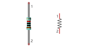
The bands of color on a resistor is a shorthand code used to identify its resistance value. For more details of resistor color codes, please refer to the appendix of this tutorial.
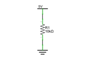
With a fixed voltage, there will be less current output with greater resistance added to the circuit. The relationship between Current, Voltage and Resistance can be expressed by this formula: I=V/R known as Ohm’s Law where I = Current, V = Voltage and R = Resistance. Knowing the values of any two of these allows you to solve the value of the third.
In the following diagram, the current through R1 is: I=U/R=5V/10kΩ=0.0005A=0.5mA.
WARNING: Never connect the two poles of a power supply with anything of low resistance value (i.e. a metal object or bare wire) this is a Short and results in high current that may damage the power supply and electronic components.
Note: Unlike LEDs and diodes, resistors have no poles and re non-polar (it does not matter which direction you insert them into a circuit, it will work the same)
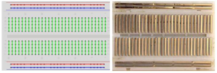
Breadboard
Here we have a small breadboard as an example of how the rows of holes (sockets) are electrically attached.
The left picture shows the way to connect pins. The right picture shows the practical internal structure.
Power
ESP8266 needs 5v power supply. In this tutorial, we need connect ESP8266 to computer via USB cable to power it and program it. We can also use other 5v power source to power it.
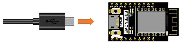
In the following projects, we only use USB cable to power ESP8266 by default.
Circuit
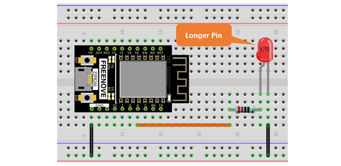
First, disconnect all power from the ESP8266. Then build the circuit according to the circuit and hardware diagrams. After the circuit is built and verified correct, connect the PC to ESP8266.
CAUTION: Avoid any possible short circuits (especially connecting 5V or GND, 3.3V and GND)! WARNING: A short circuit can cause high current in your circuit, generate excessive component heat and cause permanent damage to your hardware!
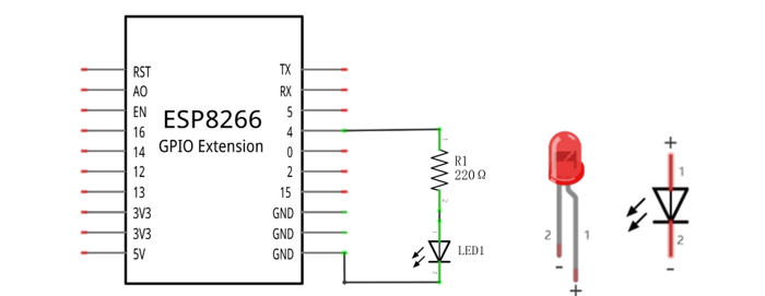
Schematic diagram |
|
Hardware connection If you need any support, please feel free to contact us via: support@freenove.com |
|
Sketch
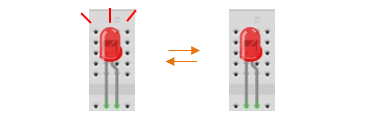
According to the circuit, when the GPIO4 of ESP8266 output level is high, the LED turns ON. Conversely, when the GPIO4 ESP8266 output level is low, the LED turns OFF. Therefore, we can let GPIO4 circularly output high and low level to make the LED blink.
Upload the following Sketch:
Freenove_Ultimate_Starter_Kit_for_ESP8266\C\Sketches\Sketch_01.1_Blink2
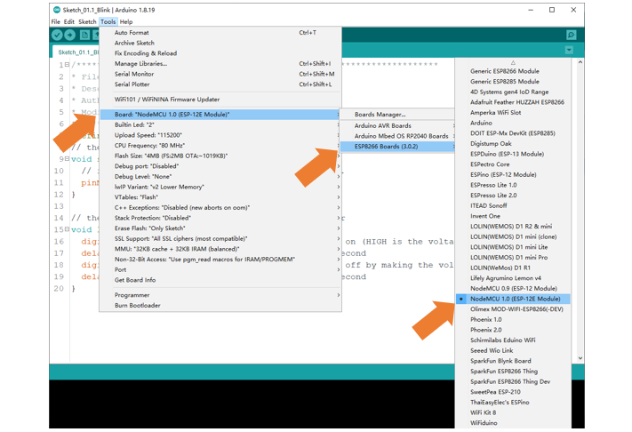
Before uploading the code, click “Tools”, “Board” and select “NodeMCU 1.0(ESP-12E Module)”.
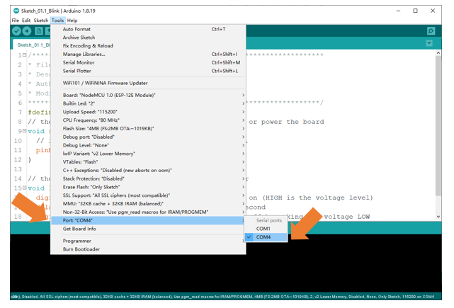
Select the serial port.
Note
For macOS users, if the uploading fails, please set the baud rate to 115200 before clicking “Upload Using Programmer”.
Sketch_01.1_Blink2
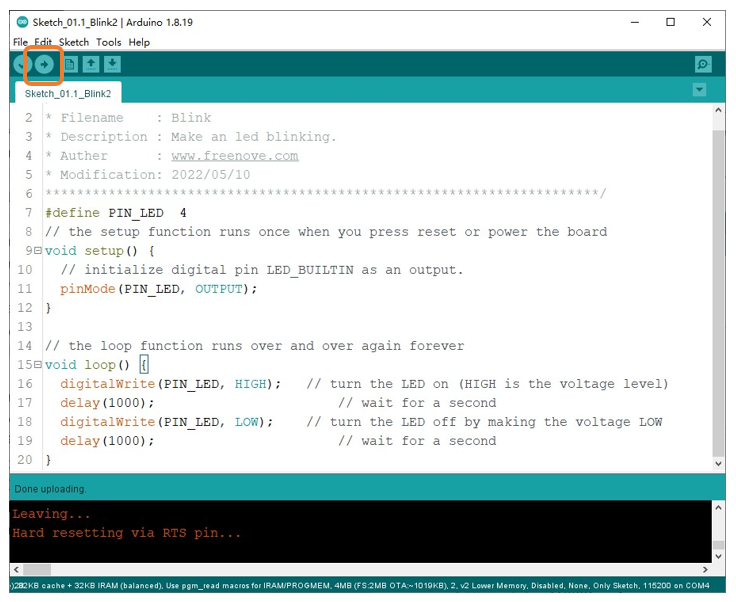
Click “Upload”, Download the code to ESP8266 and your LED in the circuit starts Blink.
If you have any concerns, please contact us via: support@freenove.com
The following is the program code:
 1/**********************************************************************
 2* Filename    : Blink
 3* Description : Make an led blinking.
 4* Auther      : www.freenove.com
 5* Modification: 2022/05/10
 6**********************************************************************/
 7#define PIN_LED  4
 8// the setup function runs once when you press reset or power the board
 9void setup() {
10  // initialize digital pin LED_BUILTIN as an output.
11  pinMode(PIN_LED, OUTPUT);
12}
13
14// the loop function runs over and over again forever
15void loop() {
16  digitalWrite(PIN_LED, HIGH);   // turn the LED on (HIGH is the voltage level)
17  delay(1000);                       // wait for a second
18  digitalWrite(PIN_LED, LOW);    // turn the LED off by making the voltage LOW
19  delay(1000);                       // wait for a second
20}