9. Chapter Photoresistor & LED
In this chapter, we will learn how to use a photoresistor to make an automatic dimming nightlight.
9.1. Project NightLamp
A Photoresistor is very sensitive to the amount of light present. We can take advantage of the characteristic to make a nightlight with the following function. When the ambient light is less (darker environment), the LED will automatically become brighter to compensate and when the ambient light is greater (brighter environment) the LED will automatically dim to compensate.
9.1.1. Component List
|
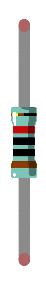
Resistor 220Ω x1
|
Photoresistor x1
|
|
ADC module x1 (Only one)
|
LED x1
|
Jumper Wire M/M x15 |
|


9.1.2. Component knowledge
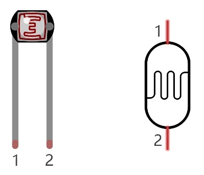
9.1.2.1. Photoresistor
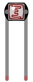
A Photoresistor is simply a light sensitive resistor. It is an active component that decreases resistance with respect to receiving luminosity (light) on the component’s light sensitive surface. A Photoresistor’s resistance value will change in proportion to the ambient light detected. With this characteristic, we can use a Photoresistor to detect light intensity. The Photoresistor and its electronic symbol are as follows.
The circuit below is used to detect the change of a Photoresistor’s resistance value:
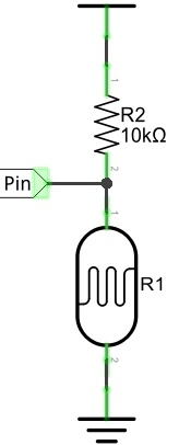
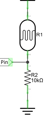
In the above circuit, when a Photoresistor’s resistance vale changes due to a change in light intensity, the voltage between the Photoresistor and Resistor R1 will also change. Therefore, the intensity of the light can be obtained by measuring this voltage.
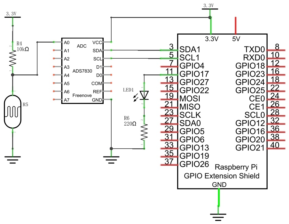
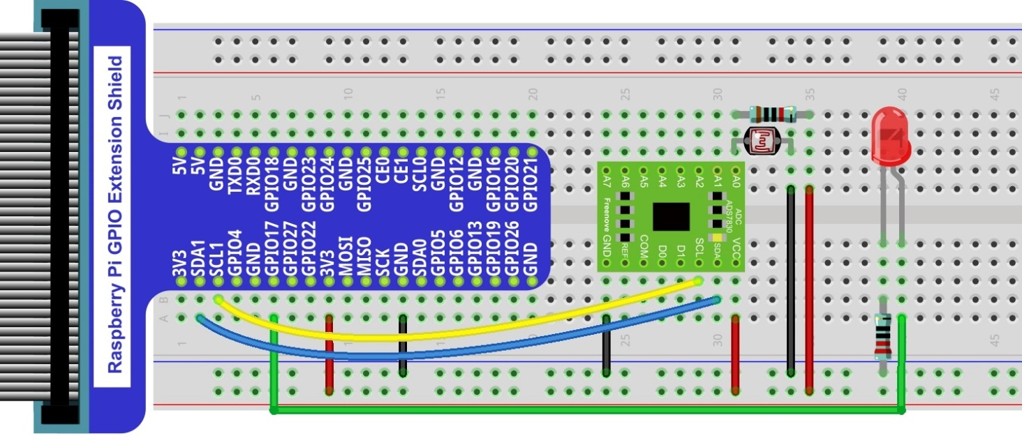
9.1.3. Circuit with ADS7830
The circuit used is similar to the Soft light project. The only difference is that the input signal of the AIN0 pin of ADC changes from a Potentiometer to a combination of a Photoresistor and a Resistor.
Schematic diagram
|
Hardware connection. If you need any support,please feel free to contact us via:
|
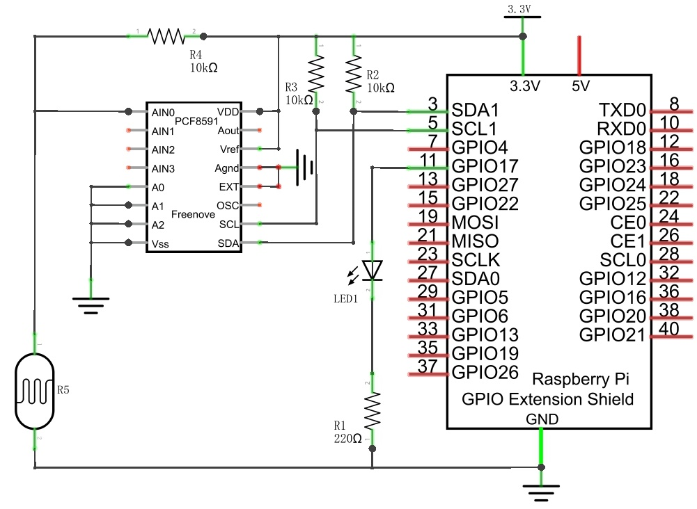
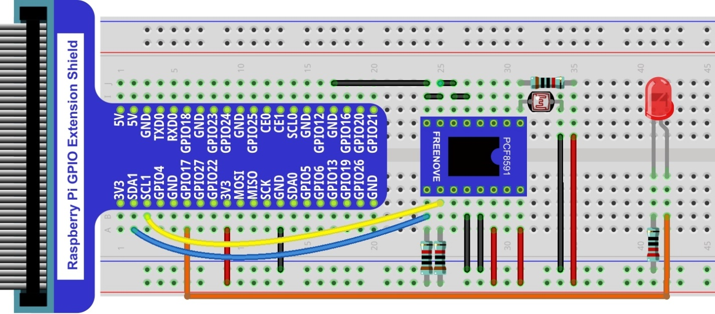
9.1.4. Circuit with PCF8591
The circuit used is similar to the Soft light project. The only difference is that the input signal of the AIN0 pin of ADC changes from a Potentiometer to a combination of a Photoresistor and a Resistor.
Schematic diagram
|
Hardware connection.
|
9.1.5. Code
The code used in this project is identical with what was used in the last chapter.
9.1.5.1. Python Code Nightlamp
If you did not configure I2C, please refer to Chapter 7. If you did, please continue.
First, observe the project result, and then learn about the code in detail.
Hint
If you have any concerns, please contact us via: support@freenove.com
Use cd command to enter 10.1_Nightlamp directory of Python code.
$ cd ~/Freenove_Kit/Code/Python_GPIOZero_Code/9.1.1_Nightlamp
Use the python command to execute the Python code “Nightlamp.py”.
$ python Nightlamp.py
After the program is executed, if you cover the Photoresistor or increase the light shining on it, the brightness of the LED changes accordingly. As in previous projects the Terminal window will display the current input voltage value of ADC module A0 pin and the converted digital quantity.
The following is the program code: