20. Chapter LCD1602
In this chapter, we will learn about the LCD1602 Display Screen
20.1. Project I2C LCD1602
There are LCD1602 display screen and the I2C LCD. We will introduce both of them in this chapter. But what we use in this project is an I2C LCD1602 display screen. The LCD1602 Display Screen can display 2 lines of characters in 16 columns. It is capable of displaying numbers, letters, symbols, ASCII code and so on. As shown below is a monochrome LCD1602 Display Screen along with its circuit pin diagram

I2C LCD1602 Display Screen integrates a I2C interface, which connects the serial-input & parallel-output module to the LCD1602 Display Screen. This allows us to only use 4 lines to operate the LCD1602.

The serial-to-parallel IC chip used in this module is PCF8574T (PCF8574AT), and its default I2C address is 0x27(0x3F). You can also view the RPI bus on your I2C device address through command “i2cdetect -y 1” (refer to the “configuration I2C” section below).
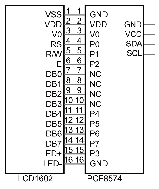
Below is the PCF8574 chip pin diagram and its module pin diagram:

PCF8574 module pins and LCD1602 pins correspond to each other and connected to each other:
Because of this, as stated earlier, we only need 4 pins to control the16 pins of the LCD1602 Display Screen through the I2C interface.
In this project, we will use the I2C LCD1602 to display some static characters and dynamic variables.
20.1.1. Component List
|
Jumper Wires x4 |
I2C LCD1602 Module x1 |
|


20.1.2. Circuit
Note that the power supply for I2C LCD1602 in this circuit is 5V.
Schematic diagram
|
Hardware connection. If you need any support,please feel free to contact us via:
|


Note
It is necessary to configure 12C and install Smbus first (see Chapter 7 ADC for details)
20.1.3. Code
This code will have your RPi’s CPU temperature and System Time Displayed on the LCD1602.
20.1.3.1. C Code I2CLCD1602
If you did not configure I2C and install Smbus, please refer to Chapter 7. If you did, please continue.
First, observe the project result, and then learn about the code in detail.
Hint
If you have any concerns, please contact us via: support@freenove.com
Use
cdcommand to enter20.1.1_ I2CLCD1602directory of C code.
$ cd ~/Freenove_Kit/Code/C_Code/20.1.1_I2CLCD1602
Use following command to compile “I2CLCD1602.c” and generate executable file
I2CLCD1602.
$ gcc I2CLCD1602.c -o I2CLCD1602 -lwiringPi -lwiringPiDev
Then run the generated file “I2CLCD1602”.
$ sudo ./I2CLCD1602
After the program is executed, the LCD1602 Screen will display your RPi’s CPU Temperature and System Time.
So far, at this writing, we have two types of LCD1602 on sale. One needs to adjust the backlight, and the other does not.
The LCD1602 that does not need to adjust the backlight is shown in the figure below.

The following is the program code:
  1/**********************************************************************
  2* Filename    : I2CLCD1602.c
  3* Description : Use the LCD display data
  4* Author      : www.freenove.com
  5* modification: 2020/07/23
  6**********************************************************************/
  7#include <stdlib.h>
  8#include <stdio.h>
  9#include <wiringPi.h>
 10#include <wiringPiI2C.h>
 11#include <pcf8574.h>
 12#include <lcd.h>
 13#include <time.h>
 14
 15int pcf8574_address = 0x27;        // PCF8574T:0x27, PCF8574AT:0x3F
 16#define BASE 64         // BASE any number above 64
 17//Define the output pins of the PCF8574, which are directly connected to the LCD1602 pin.
 18#define RS      BASE+0
 19#define RW      BASE+1
 20#define EN      BASE+2
 21#define LED     BASE+3
 22#define D4      BASE+4
 23#define D5      BASE+5
 24#define D6      BASE+6
 25#define D7      BASE+7
 26
 27int lcdhd;// used to handle LCD
 28void printCPUTemperature(){// sub function used to print CPU temperature
 29    FILE *fp;
 30    char str_temp[15];
 31    float CPU_temp;
 32    // CPU temperature data is stored in this directory.
 33    fp=fopen("/sys/class/thermal/thermal_zone0/temp","r");
 34    fgets(str_temp,15,fp);      // read file temp
 35    CPU_temp = atof(str_temp)/1000.0;   // convert to Celsius degrees
 36    printf("CPU's temperature : %.2f \n",CPU_temp);
 37    lcdPosition(lcdhd,0,0);     // set the LCD cursor position to (0,0)
 38    lcdPrintf(lcdhd,"CPU:%.2fC",CPU_temp);// Display CPU temperature on LCD
 39    fclose(fp);
 40}
 41void printDataTime(){//used to print system time
 42    time_t rawtime;
 43    struct tm *timeinfo;
 44    time(&rawtime);// get system time
 45    timeinfo = localtime(&rawtime);//convert to local time
 46    printf("%s \n",asctime(timeinfo));
 47    lcdPosition(lcdhd,0,1);// set the LCD cursor position to (0,1)
 48    lcdPrintf(lcdhd,"Time:%02d:%02d:%02d",timeinfo->tm_hour,timeinfo->tm_min,timeinfo->tm_sec); //Display system time on LCD
 49}
 50int detectI2C(int addr){
 51    int _fd = wiringPiI2CSetup (addr);
 52    if (_fd < 0){
 53        printf("Error address : 0x%x \n",addr);
 54        return 0 ;
 55    }
 56    else{
 57        if(wiringPiI2CWrite(_fd,0) < 0){
 58            printf("Not found device in address 0x%x \n",addr);
 59            return 0;
 60        }
 61        else{
 62            printf("Found device in address 0x%x \n",addr);
 63            return 1 ;
 64        }
 65    }
 66}
 67int main(void){
 68    int i;
 69
 70    printf("Program is starting ...\n");
 71
 72    wiringPiSetup();
 73    if(detectI2C(0x27)){
 74        pcf8574_address = 0x27;
 75    }else if(detectI2C(0x3F)){
 76        pcf8574_address = 0x3F;
 77    }else{
 78        printf("No correct I2C address found, \n"
 79        "Please use command 'i2cdetect -y 1' to check the I2C address! \n"
 80        "Program Exit. \n");
 81        return -1;
 82    }
 83    pcf8574Setup(BASE,pcf8574_address);//initialize PCF8574
 84    for(i=0;i<8;i++){
 85        pinMode(BASE+i,OUTPUT);     //set PCF8574 port to output mode
 86    }
 87    digitalWrite(LED,HIGH);     //turn on LCD backlight
 88    digitalWrite(RW,LOW);       //allow writing to LCD
 89	lcdhd = lcdInit(2,16,4,RS,EN,D4,D5,D6,D7,0,0,0,0);// initialize LCD and return “handle” used to handle LCD
 90    if(lcdhd == -1){
 91        printf("lcdInit failed !");
 92        return 1;
 93    }
 94    while(1){
 95        printCPUTemperature();//print CPU temperature
 96        printDataTime();        // print system time
 97        delay(1000);
 98    }
 99    return 0;
100}
From the code, we can see that the PCF8591 and the PCF8574 have many similarities in using the I2C interface to expand the GPIO RPI.
First, define the I2C address of the PCF8574 and the Extension of the GPIO pin, which is connected to the GPIO pin of the LCD1602. LCD1602 has two different i2c addresses. Set 0x27 as default.
 1int pcf8574_address = 0x27;        // PCF8574T:0x27, PCF8574AT:0x3F
 2#define BASE 64         // BASE any number above 64
 3//Define the output pins of the PCF8574, which are directly connected to the LCD1602 pin.
 4#define RS      BASE+0
 5#define RW      BASE+1
 6#define EN      BASE+2
 7#define LED     BASE+3
 8#define D4      BASE+4
 9#define D5      BASE+5
10#define D6      BASE+6
11#define D7      BASE+7
Then, in main function, initialize the PCF8574, set all the pins to output mode, and turn ON the LCD1602 backlight (without the backlight the Display is difficult to read).
1pcf8574Setup(BASE,pcf8574_address);//initialize PCF8574
2for(i=0;i<8;i++){
3    pinMode(BASE+i,OUTPUT);     //set PCF8574 port to output mode
4}
5digitalWrite(LED,HIGH);     //turn on LCD backlight
Then use lcdInit() to initialize LCD1602 and set the RW pin of LCD1602 to 0 (can be written) according to requirements of this function. The return value of the function called “Handle” is used to handle LCD1602”.
1lcdhd = lcdInit(2,16,4,RS,EN,D4,D5,D6,D7,0,0,0,0);// initialize LCD and return "handle" used to handle LCD
Details about lcdInit():
-
int lcdInit(int rows, int cols, int bits, int rs, int strb, int d0, int d1, int d2, int d3, int d4, int d5, int d6, int d7);
This is the main initialization function and must be executd first before you use any other LCD functions. Rows and cols are the rows and columns of the Display (e.g. 2, 16 or 4, 20). Bits is the number of how wide the number of bits is on the interface (4 or 8). The rs and strb represent the pin numbers of the Display’s RS pin and Strobe (E) pin. The parameters d0 through d7 are the pin numbers of the 8 data pins connected from the RPi to the display. Only the first 4 are used if you are running the display in 4-bit mode.
The return value is the ‘handle’ to be used for all subsequent calls to the lcd library when dealing with that LCD, or -1 to indicate a fault (usually incorrect parameter)
For more details about LCD Library, please refer to: https://projects.drogon.net/raspberry-pi/wiringpi/lcd-library/
In the next “while”, two subfunctions are called to display the RPi’s CPU Temperature and the SystemTime. First look at subfunction printCPUTemperature(). The CPU temperature data is stored in the “/sys/class/thermal/thermal_zone0/temp” file. We need to read the contents of this file, which converts it to temperature value stored in variable CPU_temp and uses lcdPrintf() to display it on LCD.
 1void printCPUTemperature(){// sub function used to print CPU temperature
 2    FILE *fp;
 3    char str_temp[15];
 4    float CPU_temp;
 5    // CPU temperature data is stored in this directory.
 6    fp=fopen("/sys/class/thermal/thermal_zone0/temp","r");
 7    fgets(str_temp,15,fp);      // read file temp
 8    CPU_temp = atof(str_temp)/1000.0;   // convert to Celsius degrees
 9    printf("CPU's temperature : %.2f \n",CPU_temp);
10    lcdPosition(lcdhd,0,0);     // set the LCD cursor position to (0,0)
11    lcdPrintf(lcdhd,"CPU:%.2fC",CPU_temp);// Display CPU temperature on LCD
12    fclose(fp);
13}
Details about lcdPosition() and lcdPrintf():
- lcdPosition (int handle, int x, int y);
Set the position of the cursor for subsequent text entry.
- lcdPutchar(int handle, uint8_t data) & lcdPuts (int handle, char *string) & lcdPrintf (int handle, char *message, …)
These output a single ASCII character, a string or a formatted string using the usual print formatting commands to display individual characters (it is how you are able to see characters on your computer monitor).
Next is subfunction printDataTime() used to display System Time. First, it gets the Standard Time and stores it into variable Rawtime, and then converts it to the Local Time and stores it into timeinfo, and finally displays the Time information on the LCD1602 Display.
1void printDataTime(){//used to print system time
2    time_t rawtime;
3    struct tm *timeinfo;
4    time(&rawtime);// get system time
5    timeinfo = localtime(&rawtime);//convert to local time
6    printf("%s \n",asctime(timeinfo));
7    lcdPosition(lcdhd,0,1);// set the LCD cursor position to (0,1)
8    lcdPrintf(lcdhd,"Time:%02d:%02d:%02d",timeinfo->tm_hour,timeinfo->tm_min,timeinfo->tm_sec); //Display system time on LCD
9}