15. Chapter 74HC595 & Bar Graph LED
We have used LED Bar Graph to make a flowing water light, in which 10 GPIO ports of RPi are occupied. More GPIO ports mean that more peripherals can be connected to RPi, so GPIO resource is very precious. Can we make flowing water light with less GPIO ports? In this chapter, we will learn a component, 74HC595, which can achieve the target.
15.1. Project FollowLight
Now let us learn how to use the 74HC595 IC Chip to make a flowing water light using less GPIO.
15.1.1. Component List
|
Jumper Wires x17 |
||
74HC595 x1 |
Bar Graph LED x1 |
Resistor 220Ω x8 |
|


15.1.2. Component knowledge
A 74HC595 chip is used to convert serial data into parallel data. A 74HC595 chip can convert the serial data of one byte into 8 bits, and send its corresponding level to each of the 8 ports correspondingly. With this characteristic, the 74HC595 chip can be used to expand the IO ports of a Raspberry Pi. At least 3 ports on the RPI board are required to control the 8 ports of the 74HC595 chip.
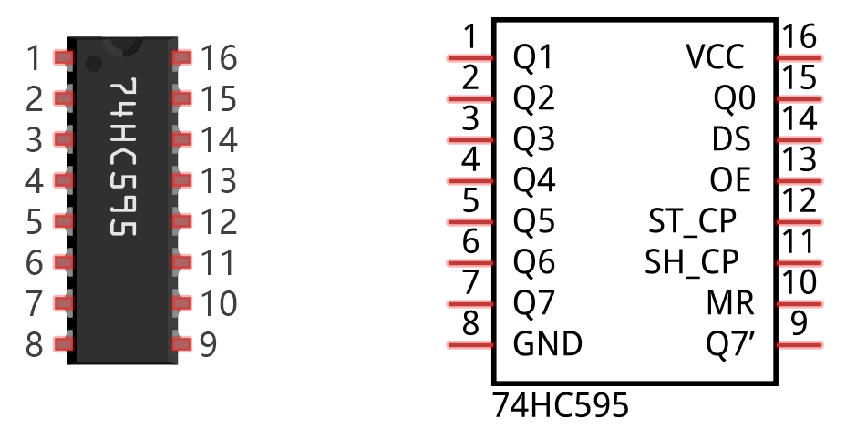
The ports of the 74HC595 chip are described as follows:
Pin name |
Pin number |
Description |
|---|---|---|
Q0-Q7 |
15, 1-7 |
Parallel Data Output |
VCC |
16 |
The Positive Electrode of the Power Supply, the Voltage is 2~6V |
GND |
8 |
The Negative Electrode of Power Supply |
DS |
14 |
Serial Data Input |
OE |
13 |
Enable Output, When this pin is in high level, Q0-Q7 is in high resistance state When this pin is in low level, Q0-Q7 is in output mode |
ST_CP |
12 |
Parallel Update Output: when its electrical level is rising, it will update the parallel data output. |
SH_CP |
11 |
Serial Shift Clock: when its electrical level is rising, it will update the parallel data output. |
MR |
10 |
Remove Shift Register: When this pin is in low level, the content in shift register will be cleared. |
Q7 |
9 |
Serial Data Output: it can be connected to more 74HC595 chips in series. |
See also
For more details, please refer to the datasheet on the 74HC595 chip.
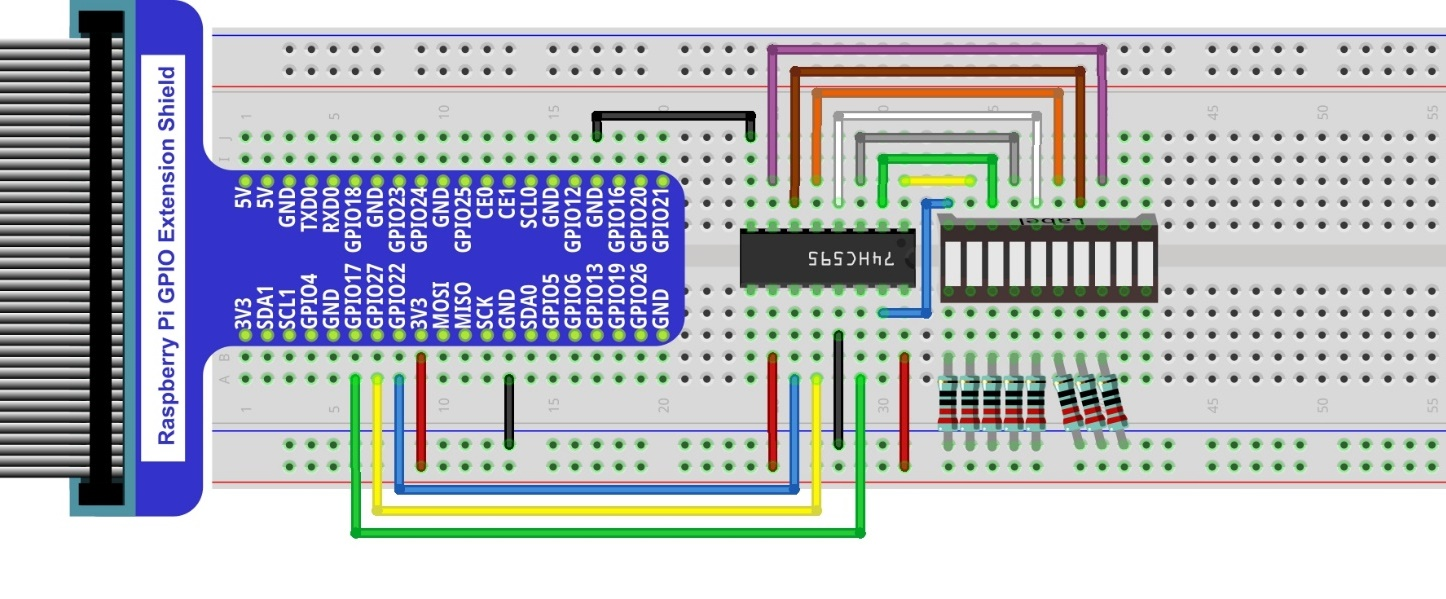
15.1.3. Circuit
Schematic diagram
|
Hardware connection. If you need any support,please feel free to contact us via:
|

15.1.4. Sketch
In this chapter, we will learn how to drive the LED Bar by expanding the chip.
15.1.4.1. Sketch_FlowingLight02
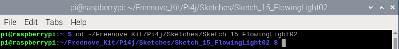
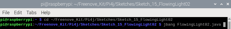
First, enter where the project is located:
$ cd ~/Freenove_Kit/Pi4j/Sketches/Sketch_15_FlowingLight02
Enter the command to run the code.
$ jbang FlowingLight02.java
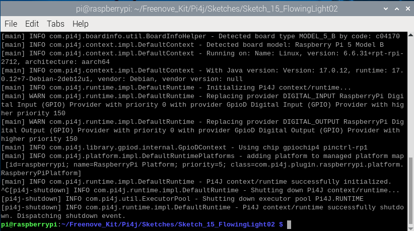
When the code is running, you can see the LEDs of the LED bar light up in a flowing water pattern.
Press Ctrl+C to exit the program.
You can run the following command to open the code with Geany to view and edit it.
$ geany FlowingLight02.java
Click the icon to run the code.
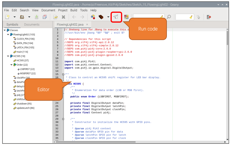
If the code fails to run, please check Geany Configuration.
The following is program code:
  1///usr/bin/env jbang "$0" "$@" ; exit $?
  2
  3//DEPS org.slf4j:slf4j-api:2.0.12
  4//DEPS org.slf4j:slf4j-simple:2.0.12
  5//DEPS com.pi4j:pi4j-core:2.6.0
  6//DEPS com.pi4j:pi4j-plugin-raspberrypi:2.6.0
  7//DEPS com.pi4j:pi4j-plugin-gpiod:2.6.0
  8
  9import com.pi4j.Pi4J;
 10import com.pi4j.context.Context;
 11import com.pi4j.io.gpio.digital.DigitalOutput;
 12
 13class HC595 {
 14    public enum Order {LSBFIRST, MSBFIRST};
 15    private final DigitalOutput dataPin;
 16    private final DigitalOutput latchPin;
 17    private final DigitalOutput clockPin;
 18    private final Context pi4j;
 19
 20    public HC595(Context pi4j, int dataPin, int latchPin, int clockPin) {
 21        this.pi4j = pi4j;
 22        this.dataPin = pi4j.dout().create(dataPin);
 23        this.latchPin = pi4j.dout().create(latchPin);
 24        this.clockPin = pi4j.dout().create(clockPin);
 25    }
 26
 27    private static void delayUs(long us) {
 28        long startTime = System.nanoTime();
 29        long endTime = startTime + (us * 1000);
 30        while (System.nanoTime() < endTime) {
 31        }
 32    }
 33
 34    public void shiftOut(Order order, int val) {
 35        int i;
 36        for (i = 0; i < 8; i++) {
 37            clockPin.low();
 38            if (order == Order.LSBFIRST) {
 39                if ((0x01 & (val >> i)) == 0x01) {
 40                    dataPin.high();
 41                } else {
 42                    dataPin.low();
 43                }
 44            } else {
 45                if ((0x80 & (val << i)) == 0x80) {
 46                    dataPin.high();
 47                } else {
 48                    dataPin.low();
 49                }
 50            }
 51            clockPin.high();
 52        }
 53    }
 54
 55    public void updateLatch() {
 56        latchPin.low();
 57        delayUs(1);
 58        latchPin.high();
 59    }
 60
 61    public void shutdown() {
 62        pi4j.shutdown();
 63    }
 64}
 65
 66public class FlowingLight02 {
 67    private static final int DATA_PIN = 22;
 68    private static final int LATCH_PIN = 27;
 69    private static final int CLOCK_PIN = 17;
 70
 71    public static void main(String[] args) throws Exception {
 72        var pi4j = Pi4J.newAutoContext();
 73        HC595 ledbar = new HC595(pi4j, DATA_PIN, LATCH_PIN, CLOCK_PIN);
 74
 75        try {
 76            int x;
 77            while (true) {
 78                x = 0x0001;
 79                for (int i = 0; i < 10; i++) {
 80                    ledbar.shiftOut(HC595.Order.MSBFIRST, (x >> 8) & 0xff); // Dummy shift for higher bits
 81                    ledbar.shiftOut(HC595.Order.MSBFIRST, x & 0xff);
 82                    ledbar.updateLatch();
 83                    x <<= 1;
 84                    Thread.sleep(100);
 85                }
 86
 87                x = 0x0200;
 88                for (int i = 0; i < 10; i++) {
 89                    ledbar.shiftOut(HC595.Order.MSBFIRST, (x >> 8) & 0xff); // Dummy shift for higher bits
 90                    ledbar.shiftOut(HC595.Order.MSBFIRST, x & 0xff);
 91                    ledbar.updateLatch();
 92                    x >>= 1;
 93                    Thread.sleep(100);
 94                }
 95            }
 96        } finally {
 97            ledbar.shutdown();
 98        }
 99    }
100}
Define the data transfer order for enumeration types.
public enum Order {LSBFIRST, MSBFIRST};
Define the data pin, latch pin, clock pin, and Pi4j context.
1private final DigitalOutput dataPin;
2private final DigitalOutput latchPin;
3private final DigitalOutput clockPin;
4private final Context pi4j;
Constructor, initialize pins and context.
1public HC595(Context pi4j, int dataPin, int latchPin, int clockPin) {
2    this.pi4j = pi4j;
3    this.dataPin = pi4j.dout().create(dataPin);
4    this.latchPin = pi4j.dout().create(latchPin);
5    this.clockPin = pi4j.dout().create(clockPin);
6}
Delay function in microsecond.
1private static void delayUs(long us) {
2    long startTime = System.nanoTime();
3    long endTime = startTime + (us * 1000);
4    while (System.nanoTime() < endTime) {
5    }
6}
Shift function for expansion chip. The Raspberry Pi sends data to the extended chip through GPIO.
 1public void shiftOut(Order order, int val) {
 2    int i;
 3    for (i = 0; i < 8; i++) {
 4        clockPin.low();
 5        if (order == Order.LSBFIRST) {
 6            if ((0x01 & (val >> i)) == 0x01) {
 7                dataPin.high();
 8            } else {
 9                dataPin.low();
10            }
11        } else {
12            if ((0x80 & (val << i)) == 0x80) {
13                dataPin.high();
14            } else {
15                dataPin.low();
16            }
17        }
18        clockPin.high();
19    }
20}
Update the expansion chip latch to let the expansion chip output the signal. Usually you need to first call the shiftOut function to input data to the expansion chip, and then call the updateLatch function to have the expansion chip output the signal level corresponding to the data.
1public void updateLatch() {
2    latchPin.low();
3    delayUs(1);
4    latchPin.high();
5}
When Pi4j context is not used, shut it down to release resources.
1public void shutdown() {
2    pi4j.shutdown();
3}
Define the pin number of the driver expansion chip.
1private static final int DATA_PIN = 22;
2private static final int LATCH_PIN = 27;
3private static final int CLOCK_PIN = 17;
Create a pi4j automatic context and create an HC595 instance.
1var pi4j = Pi4J.newAutoContext();
2HC595 ledbar = new HC595(pi4j, DATA_PIN, LATCH_PIN, CLOCK_PIN);
The Raspberry Pi controls the LED bar to flow from left to right and then from right to left.
 1while (true) {
 2    x = 0x0001;
 3    for (int i = 0; i < 10; i++) {
 4        ledbar.shiftOut(HC595.Order.MSBFIRST, (x >> 8) & 0xff); // Dummy shift for higher bits
 5        ledbar.shiftOut(HC595.Order.MSBFIRST, x & 0xff);
 6        ledbar.updateLatch();
 7        x <<= 1;
 8        Thread.sleep(100);
 9    }
10
11    x = 0x0200;
12    for (int i = 0; i < 10; i++) {
13        ledbar.shiftOut(HC595.Order.MSBFIRST, (x >> 8) & 0xff); // Dummy shift for higher bits
14        ledbar.shiftOut(HC595.Order.MSBFIRST, x & 0xff);
15        ledbar.updateLatch();
16        x >>= 1;
17        Thread.sleep(100);
18    }
19}
Shutdown HC595 instance resources.
1finally {
2    ledbar.shutdown();
3}