13. Chapter Motor & Driver
In this chapter, we will learn about DC Motors and DC Motor Drivers and how to control the speed and direction of a DC Motor.
13.1. Project Control a DC Motor with a Potentiometer
In this project, a potentiometer will be used to control a DC Motor. When the Potentiometer is at the midpoint position, the DC Motor will STOP, and when the Potentiometer is turned in either direction of this midpoint, the DC Motor speed increases until it reached the endpoint where the DC Motor achieves its maximum speed. When the Potentiometer is turned “Left” of the midpoint the DC Motor will ROTATE in one direction and when turned “Right” the DC Motor will ROTATE in the opposite direction.
13.1.1. Component List
Breadboard Power Module
|
Jumper Wires x23
|
||
Breadboard Power Module x1 |
|
||
ADC module x1
|
|
||
DC Motor x1 |
Rotary Potentiometer x1 |
Resistor 10kΩ x2 |
|


13.1.2. Component knowledge
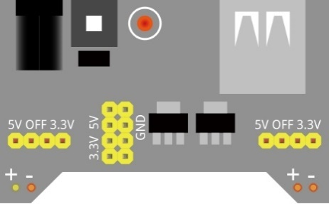
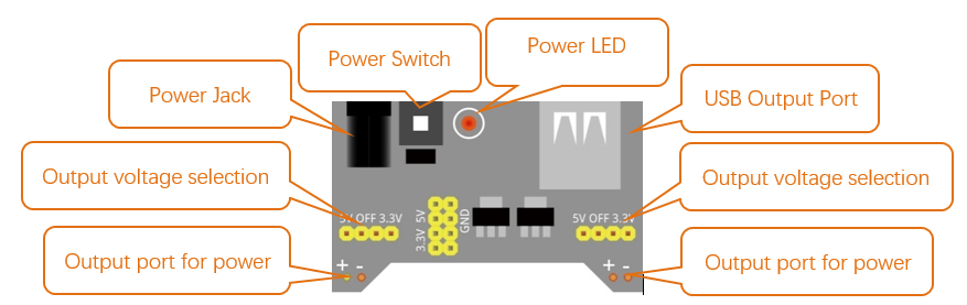
13.1.2.1. Breadboard Power Module
Breadboard Power Module is an independent circuit board, which can provide independent 5V or 3.3V power to the breadboard when building circuits. It also has built-in power protection to avoid damaging your RPi module. The schematic diagram below identifies the important features of this Power Module:
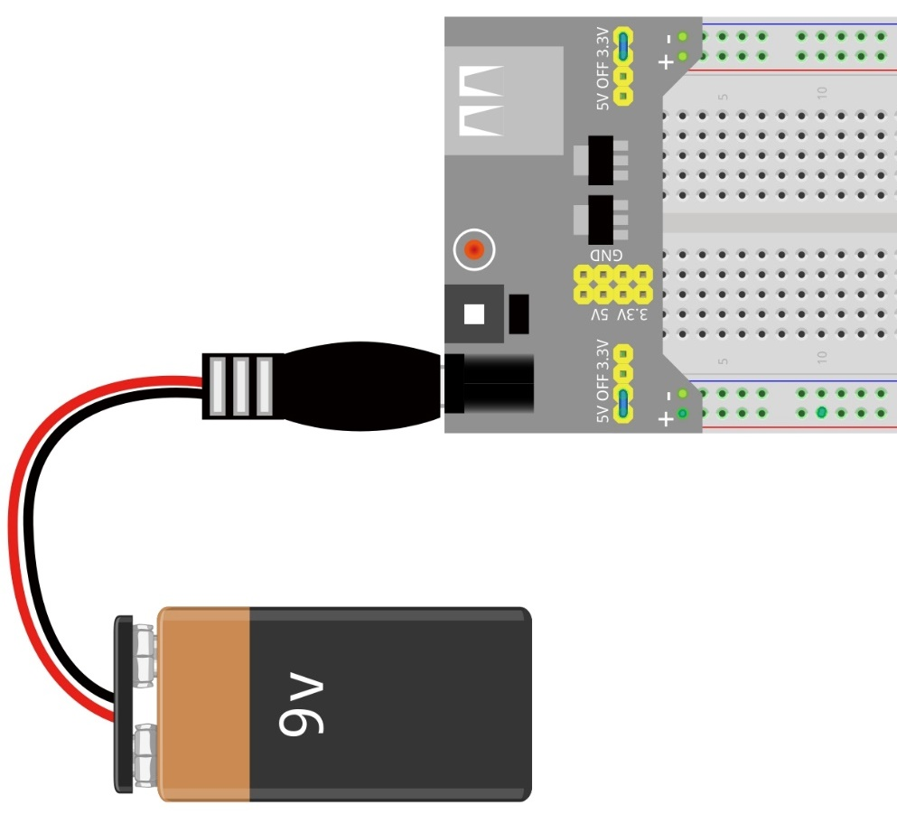
Here is an acceptable connection between Breadboard Power Module and Breadboard using a 9V battery and the provided power harness:
13.1.2.2. DC Motor
DC Motor is a device that converts electrical energy into mechanical energy. DC Motors consist of two major parts, a Stator and the Rotor. The stationary part of a DC Motor is the Stator and the part that Rotates is the Rotor. The Stator is usually part of the outer case of motor (if it is simply a pair of permanent magnets), and it has terminals to connect to the power if it is made up of electromagnet coils. Most Hobby DC Motors only use Permanent Magnets for the Stator Field. The Rotor is usually the shaft of motor with 3 or more electromagnets connected to a commutator where the brushes (via the terminals 1 & 2 below) supply electrical power, which can drive other mechanical devices. The diagram below shows a small DC Motor with two terminal pins.

When a DC Motor is connected to a power supply, it will rotate in one direction. If you reverse the polarity of the power supply, the DC Motor will rotate in opposite direction. This is important to note.

13.1.2.3. L293D
L293D is an IC Chip (Integrated Circuit Chip) with a 4-channel motor drive. You can drive a Unidirectional DC Motor with 4 ports or a Bi-Directional DC Motor with 2 ports or a Stepper Motor (Stepper Motors are covered later in this Tutorial).

Port description of L293D module is as follows:
Pin name |
Pin number |
Description |
|---|---|---|
In x |
2, 7, 10, 15 |
Channel x digital signal input pin |
Out x |
3, 6, 11, 14 |
Channel x output pin, input high or low level according to In x pin, getsconnected to +Vmotor or 0V |
Enable1 |
1 |
Channel 1 and Channel 2 enable pin, high level enable |
Enable2 |
9 |
Channel 3 and Channel 4 enable pin, high level enable |
0V |
4, 5, 12, 13 |
Power Cathode (GND) |
+V |
16 |
Positive Electrode (VCC) of power supply, supply voltage 4.5~36V |
+Vmotor |
8 |
Positive Electrode of load power supply, provide power supply for the Out pin x, the supply voltage is +V~36V |
See also
For more details, please see the datasheet for this IC Chip.
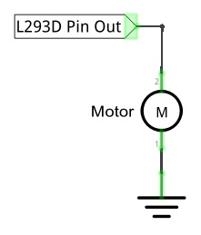
When using the L293D to drive a DC Motor, there are usually two connection options.
The following connection option uses one channel of the L239D, which can control motor speed through the PWM, However the motor then can only rotate in one direction.
The following connection uses two channels of the L239D: one channel outputs the PWM wave, and the other channel connects to GND. Therefore, you can control the speed of the motor. When these two channel signals are exchanged, not only controls the speed of motor, but also can control the direction of the motor.
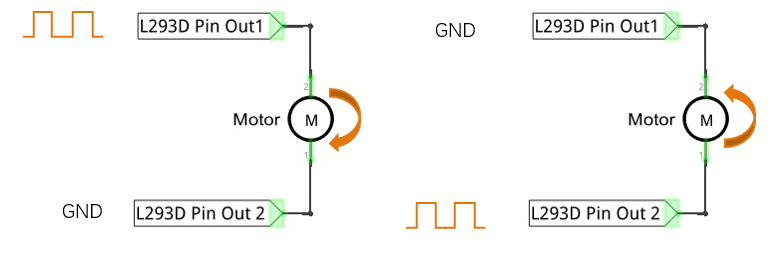
In practical use the motor is usually connected to channel 1 and by outputting different levels to in1 and in2 to control the rotational direction of the motor, and output to the PWM wave to Enable1 port to control the motor’s rotational speed. If the motor is connected to channel 3 and 4 by outputting different levels to in3 and in4 to control the motor’s rotation direction, and output to the PWM wave to Enable2 pin to control the motor’s rotational speed.
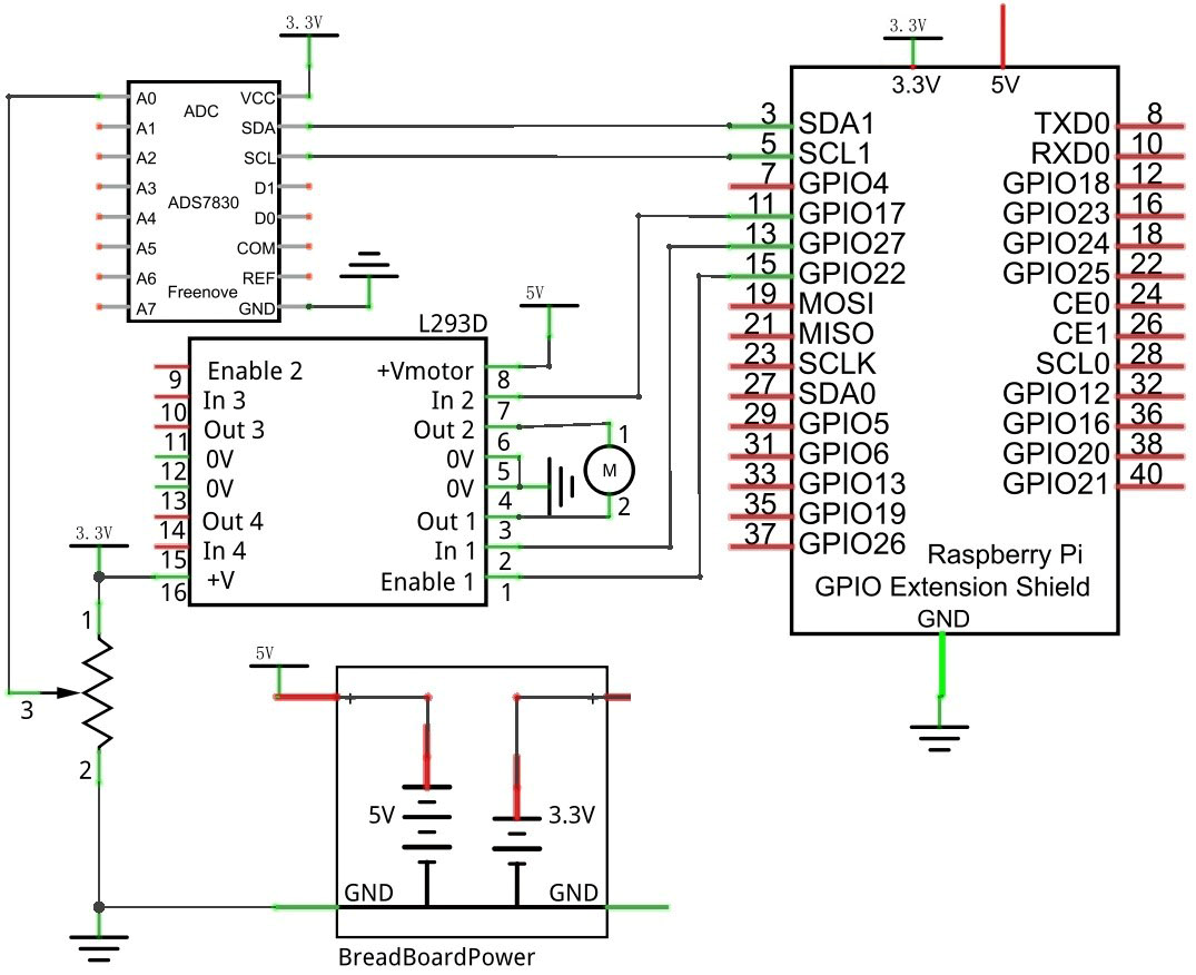
13.1.3. Circuit with ADS7830
Use caution when connecting this circuit because the DC Motor is a high-power component. Do not use the power provided by the RPi to power the motor directly, as this may cause permanent damage to your RPi! The logic circuit can be powered by the RPi’s power or an external power supply, which should share a common ground with RPi.
Schematic diagram
|
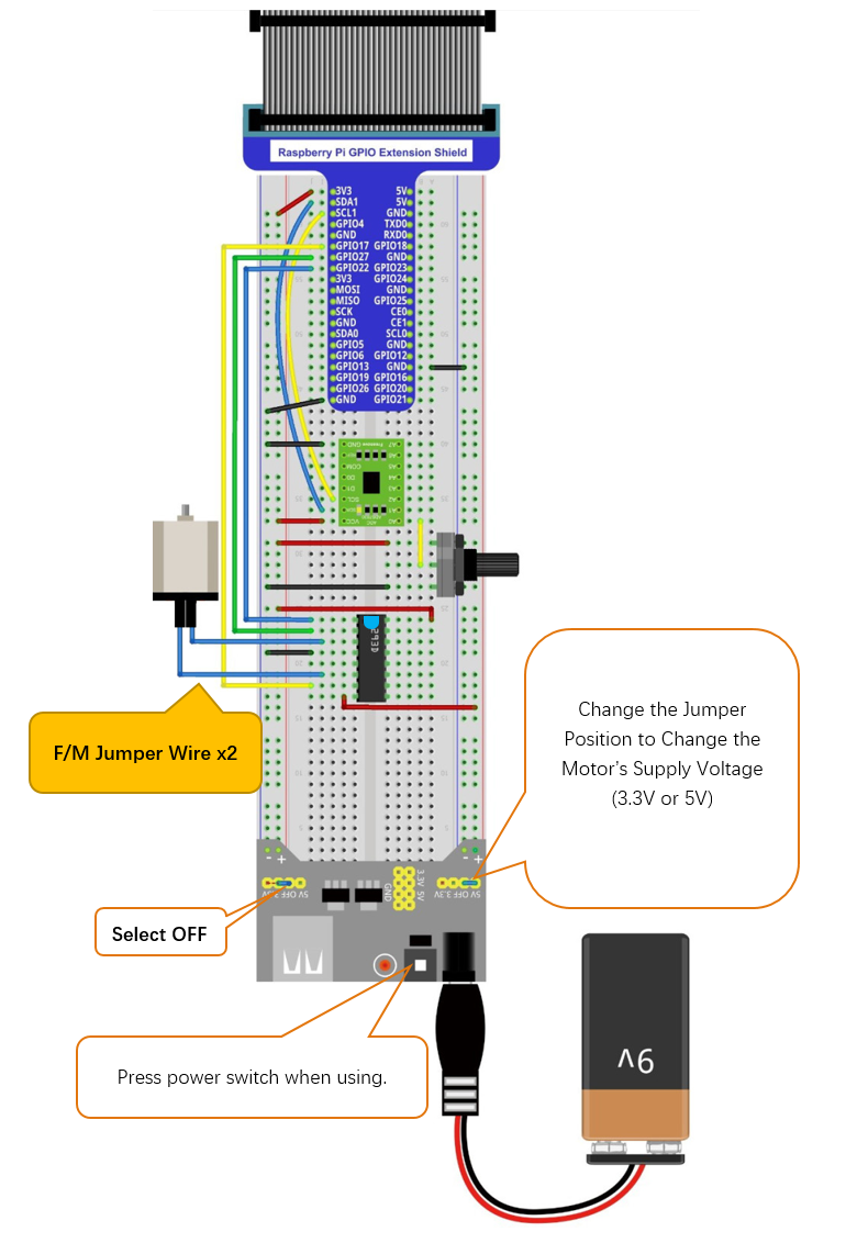
Hardware connection. If you need any support,please feel free to contact us via:
|
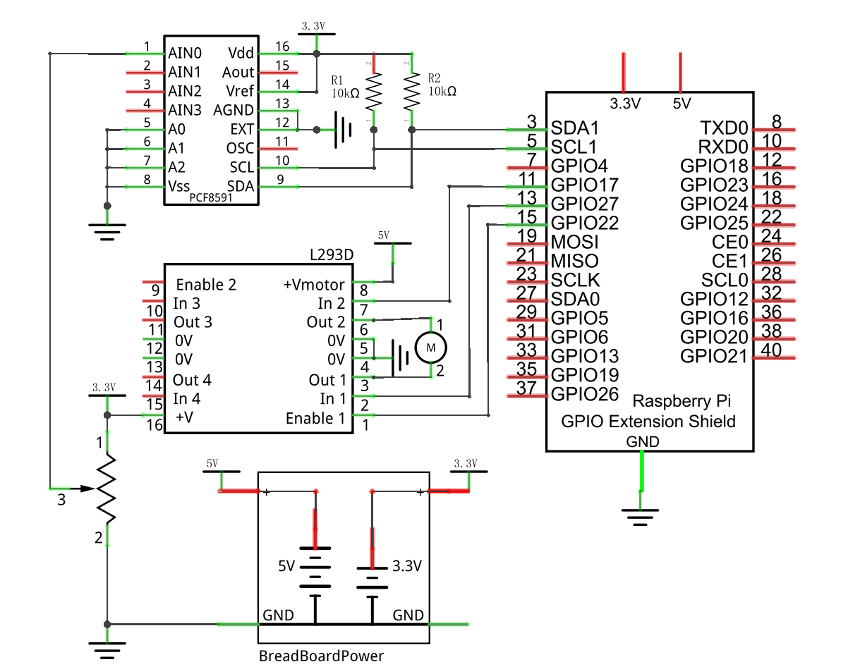
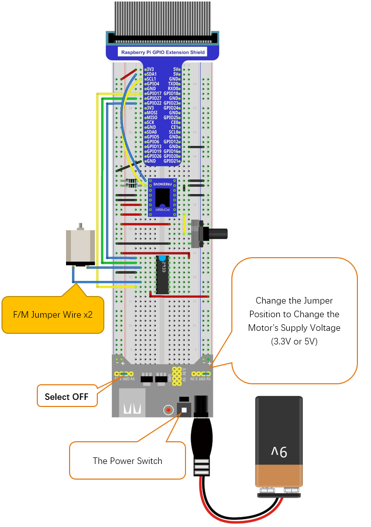
13.1.4. Circuit with PCF8591
Use caution when connecting this circuit because the DC Motor is a high-power component. Do not use the power provided by the RPi to power the motor directly, as this may cause permanent damage to your RPi!` The logic circuit can be powered by the RPi’s power or an external power supply, which should share a common ground with RPi.
Schematic diagram
|
Hardware connection. If you need any support,please feel free to contact us via:
|
13.1.5. Code
In code for this project, first read the ADC value and then control the rotation direction and speed of the DC Motor according to the value of the ADC.
13.1.5.1. C Code Motor
If you did not configure I2C, please refer to Chapter 7. If you did, please continue.
First, observe the project result, and then learn about the code in detail.
Hint
If you have any concerns, please contact us via: support@freenove.com
Use
cdcommand to enter 13.1.1_Motor directory of the C code.
$ cd ~/Freenove_Kit/Code/C_Code/13.1.1_Motor
Use the following command to compile
Motor.cppand generate the executable fileMotor.
$ g++ Motor.cpp -o Motor -lwiringPi -lADCDevice
Then run the generated file
Motor.
$ sudo ./Motor
After the program is executed, you can use the Potentiometer to control the DC Motor. When the Potentiometer is at the midpoint position, the DC Motor will STOP, and when the Potentiometer is turned in either direction of this midpoint, the DC Motor speed increases until it reaches the endpoint where the DC Motor achieves its maximum speed. When the Potentiometer is turned “Left” of the midpoint the DC Motor will ROTATE in one direction and when turned “Right” the DC Motor will ROTATE in the opposite direction. You will also see the ADC value of the potentiometer displayed in the Terminal with the motor direction and the PWM duty cycle used to control the DC Motor’s speed.

The following is the code:
 1/**********************************************************************
 2* Filename    : Motor.cpp
 3* Description : Control Motor by L293D
 4* Author      : www.freenove.com
 5* modification: 2020/03/09
 6**********************************************************************/
 7#include <wiringPi.h>
 8#include <stdio.h>
 9#include <softPwm.h>
10#include <math.h>
11#include <stdlib.h>
12#include <ADCDevice.hpp>
13
14#define motorPin1    2        //define the pin connected to L293D
15#define motorPin2    0
16#define enablePin    3
17
18ADCDevice *adc;  // Define an ADC Device class object
19
20//Map function: map the value from a range to another range.
21long map(long value,long fromLow,long fromHigh,long toLow,long toHigh){
22    return (toHigh-toLow)*(value-fromLow) / (fromHigh-fromLow) + toLow;
23}
24//motor function: determine the direction and speed of the motor according to the ADC
25void motor(int ADC){
26    int value = ADC -128;
27    if(value>0){
28        digitalWrite(motorPin1,HIGH);
29        digitalWrite(motorPin2,LOW);
30        printf("turn Forward...\n");
31    }
32    else if (value<0){
33        digitalWrite(motorPin1,LOW);
34        digitalWrite(motorPin2,HIGH);
35        printf("turn Back...\n");
36    }
37    else {
38        digitalWrite(motorPin1,LOW);
39        digitalWrite(motorPin2,LOW);
40        printf("Motor Stop...\n");
41    }
42    softPwmWrite(enablePin,map(abs(value),0,128,0,100));
43    printf("The PWM duty cycle is %d%%\n",abs(value)*100/127);//print the PMW duty cycle
44}
45int main(void){
46    adc = new ADCDevice();
47    printf("Program is starting ... \n");
48
49    if(adc->detectI2C(0x48)){    // Detect the pcf8591.
50        delete adc;                // Free previously pointed memory
51        adc = new PCF8591();    // If detected, create an instance of PCF8591.
52    }
53    else if(adc->detectI2C(0x4b)){// Detect the ads7830
54        delete adc;               // Free previously pointed memory
55        adc = new ADS7830();      // If detected, create an instance of ADS7830.
56    }
57    else{
58        printf("No correct I2C address found, \n"
59        "Please use command 'i2cdetect -y 1' to check the I2C address! \n"
60        "Program Exit. \n");
61        return -1;
62    }
63    wiringPiSetup();
64    pinMode(enablePin,OUTPUT);//set mode for the pin
65    pinMode(motorPin1,OUTPUT);
66    pinMode(motorPin2,OUTPUT);
67    softPwmCreate(enablePin,0,100);//define PMW pin
68    while(1){
69        int value = adc->analogRead(0);  //read analog value of A0 pin
70        printf("ADC value : %d \n",value);
71        motor(value);        //make the motor rotate with speed(analog value of A0 pin)
72        delay(100);
73    }
74    return 0;
75}
Now that we have familiarity with reading ADC values, let’s learn the subfunction void motor (int ADC): first, compare the ADC value with 128 (value corresponding to midpoint). When the current ADC value is higher, motoRPin1 outputs high level and motoRPin2 outputs low level to control the DC Motor to run in the “Forward” Rotational Direction. When the current ADC value is lower, motoRPin1 outputs low level and motoRPin2 outputs high level to control the DC Motor to run in the “Reverse” Rotational Direction. When the ADC value is equal to 128, motoRPin1 and motoRPin2 output low level, the motor STOPS. Then determine the PWM duty cycle according to the difference (delta) between ADC value and 128. Because the absolute delta value stays within 0-128, we need to use the map() subfunction mapping the delta value to a range of 0-255. Finally, we see a display of the duty cycle in Terminal.
 1void motor(int ADC){
 2    int value = ADC -128;
 3    if(value>0){
 4        digitalWrite(motorPin1,HIGH);
 5        digitalWrite(motorPin2,LOW);
 6        printf("turn Forward...\n");
 7    }
 8    else if (value<0){
 9        digitalWrite(motorPin1,LOW);
10        digitalWrite(motorPin2,HIGH);
11        printf("turn Back...\n");
12    }
13    else {
14        digitalWrite(motorPin1,LOW);
15        digitalWrite(motorPin2,LOW);
16        printf("Motor Stop...\n");
17    }
18    softPwmWrite(enablePin,map(abs(value),0,128,0,100));
19    printf("The PWM duty cycle is %d%%\n",abs(value)*100/127);//print the PMW duty cycle
20}