Chapter 13 74HC595 & LED Bar Graph
We have used LED bar graph to make a flowing water light, in which 10 GPIO ports of ESP8266 is occupied. More GPIO ports mean that more peripherals can be connected to ESP8266, so GPIO resource is very precious. Can we make flowing water light with less GPIO? In this chapter, we will learn a component, 74HC595, which can achieve the target.
Project 13.1 Flowing Water Light
Now let’s learn how to use the 74HC595 IC chip to make a flowing water light using less GPIO.
Component List
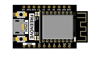
ESP8266 x1
|
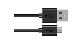
USB cable
|
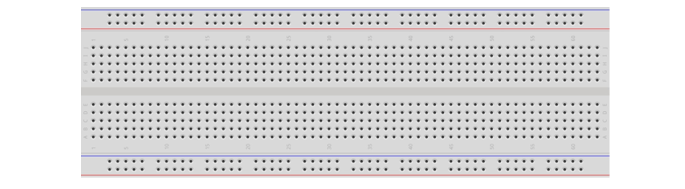
Breadboard x1
|
|
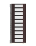
LED Bar Graph x1
|
Jumper wire M/M x17 |
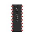
74HC595 x1
|
Resistor 220Ω x8 |
Related knowledge
74HC595
A 74HC595 chip is used to convert serial data into parallel data. A 74HC595 chip can convert the serial data of one byte into 8 bits, and send its corresponding level to each of the 8 ports correspondingly. With this characteristic, the 74HC595 chip can be used to expand the IO ports of a ESP8266. At least 3 ports are required to control the 8 ports of the 74HC595 chip.
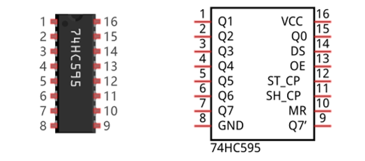
The ports of the 74HC595 chip are described as follows:
Pin name |
GPIO number |
Description |
|---|---|---|
Q0-Q7 |
15, 1-7 |
Parallel data output |
VCC |
16 |
The positive electrode of power supply, the voltage is 2~6V |
GND |
8 |
The negative electrode of power supply |
DS |
14 |
Serial data Input |
OE |
13 |
Enable output, When this pin is in high level, Q0-Q7 is in high resistance state When this pin is in low level, Q0-Q7 is in output mode |
ST_CP |
12 |
Parallel Update Output: when its electrical level is rising, it will update the parallel data output. |
SH_CP |
11 |
Serial shift clock: when its electrical level is rising, serial data input register will do a shift. |
MR |
10 |
Remove shift register: When this pin is in low level, the content in shift register will be cleared. |
Q7’ |
9 |
Serial data output: it can be connected to more 74HC595 in series. |
For more detail, please refer to the datasheet on the 74HC595 chip.
Circuit
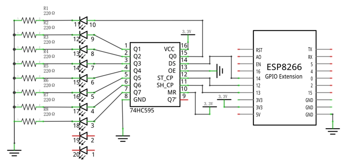
Schematic diagram |
|
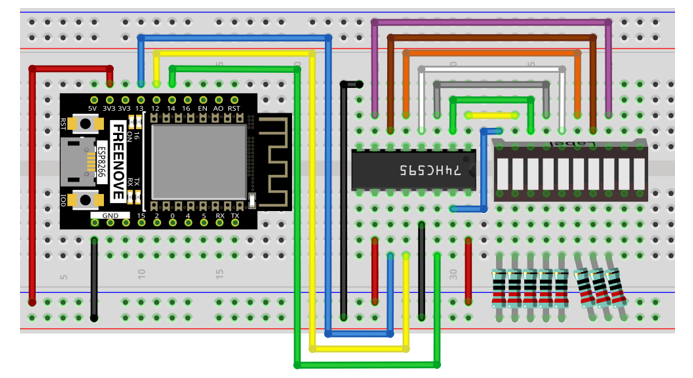
Hardware connection. If you need any support, please feel free to contact us via: support@freenove.com |
|
Sketch
In this project, we will make a flowing water light with a 74HC595 chip to learn about its functions.
Sketch_13.1_FlowingLight02
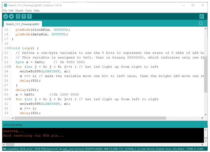
Download the code to ESP8266. You will see that LED bar graph starts with the flowing water pattern flashing from left to right and then back from right to left.
If you have any concerns, please contact us via: support@freenove.com
The following is the program code:
1/**********************************************************************
2 Filename : FlowingLight02
3 Description : Use 74HC575 to drive the ledbar to display the flowing light.
4 Auther : www.freenove.com
5 Modification: 2022/05/11
6**********************************************************************/
7
8int latchPin = 12; // Pin connected to ST_CP of 74HC595(Pin12)
9int clockPin = 13; // Pin connected to SH_CP of 74HC595(Pin13)
10int dataPin = 14; // Pin connected to DS of 74HC595(Pin14)
11
12void setup() {
13 // set pins to output
14 pinMode(latchPin, OUTPUT);
15 pinMode(clockPin, OUTPUT);
16 pinMode(dataPin, OUTPUT);
17}
18
19void loop() {
20 // Define a one-byte variable to use the 8 bits to represent the state of 8 LEDs of LED bar graph.
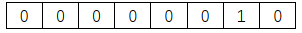
21 // This variable is assigned to 0x01, that is binary 00000001, which indicates only one LED light on.
22 byte x = 0x01; // 0b 0000 0001
23 for (int j = 0; j < 8; j++) { // Let led light up from right to left
24 writeTo595(LSBFIRST, x);
25 x <<= 1; // make the variable move one bit to left once, then the bright LED move one step to the left once.
26 delay(50);
27 }
28 delay(100);
29 x = 0x80; //0b 1000 0000
30 for (int j = 0; j < 8; j++) { // Let led light up from left to right
31 writeTo595(LSBFIRST, x);
32 x >>= 1;
33 delay(50);
34 }
35 delay(100);
36}
37void writeTo595(int order, byte _data ) {
38 // Output low level to latchPin
39 digitalWrite(latchPin, LOW);
40 // Send serial data to 74HC595
41 shiftOut(dataPin, clockPin, order, _data);
42 // Output high level to latchPin, and 74HC595 will update the data to the parallel output port.
43 digitalWrite(latchPin, HIGH);
44}
In the code, we configure three pins to control the 74HC595 chip and define a one-byte variable to control the state of the 8 LEDs (in the LED bar graph Module) through the 8 bits of the variable. The LEDs light ON when the corresponding bit is 1. If the variable is assigned to 0x01, that is 00000001 in binary, there will be only one LED ON.
1byte x = 0x01; // 0b 0000 0001
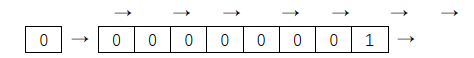
In the loop(), use “for” loop to send x to 74HC595 output pin to control the LED. In “for” loop, x will shift one bit to the LEFT in one cycle, then when data of x is sent to 74HC595, the LED that is turned ON will move one bit to the LEFT once.
1for (int j = 0; j < 8; j++) { // Let led light up from right to left
2  writeTo595(LSBFIRST, x);
3  x <<= 1; // make the variable move one bit to left once, then the bright LED move one step to the left once.
4  delay(50);
5}
In second “for” loop, the situation is the same. The difference is that x is shift from 0x80 to the RIGHT in order.
The subfunction writeTo595() is used to write data to 74HC595 and immediately output on the port of 74HC595.
Reference
- << operator
“<<” is the left shift operator, which can make all bits of 1 byte shift by several bits to the left (high) direction and add 0 on the right (low). For example, shift binary 00000001 by 1 bit to left: byte x = 1 << 1;
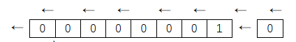
The result of x is 2(binary 00000010).
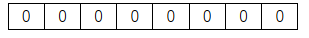
There is another similar operator” >>”. For example, shift binary 00000001 by 1 bit to right: byte x = 1 >> 1;
The result of x is (000000000).
X <<= 1 is equivalent to x = x << 1 and x >>= 1 is equivalent to x = x >> 1
- void shiftOut(uint8_t dataPin, uint8_t clockPin, uint8_t bitOrder, uint8_t val);
This is used to shift an 8-bit data value in with the data appearing on the dataPin and the clock being sent out on the clockPin. Order is as above. The data is sampled after the cPin goes high. (So clockPin high, sample data, clockPin low, repeat for 8 bits) The 8-bit value is returned by the function.
Parameters
dataPin: the pin on which to output each bit. Allowed data types: int.
clockPin: the pin to toggle once the dataPin has been set to the correct value. Allowed data types: int.
bitOrder: which order to shift out the bits; either MSBFIRST or LSBFIRST. (Most Significant Bit First, or, Least Significant Bit First).
value: the data to shift out. Allowed data types: byte.
For more details about shift function, please refer to: https://www.arduino.cc/reference/en/language/functions/advanced-io/shiftout/