Chapter 10 Potentiometer & LED
In the previous section, we have finished reading ADC value and converting it into voltage. Now, we will try
to use potentiometer to control the brightness of LED.
Project 10.1 Soft Light
In this project, we will make a soft light. We will use an ADC Module to read ADC values of a potentiometer and map it to duty cycle of the PWM used to control the brightness of a LED. Then you can change the brightness of a LED by adjusting the potentiometer.
Component List
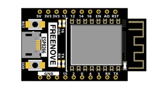
ESP8266 x1
|
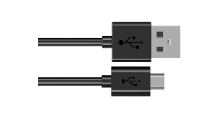
USB cable
|
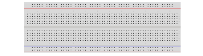
Breadboard x1
|
|
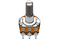
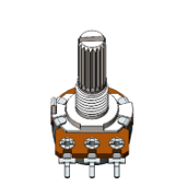
Rotary potentiometer x1
|
Jumper wire M/M x8 |
LED x1
|
Resistor 220Ω x1 |
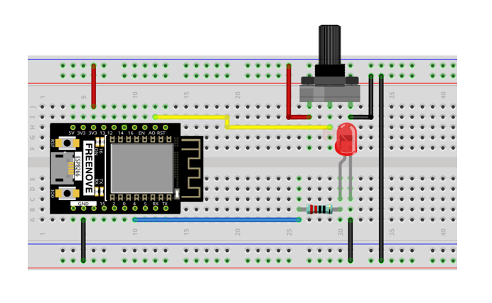
Circuit
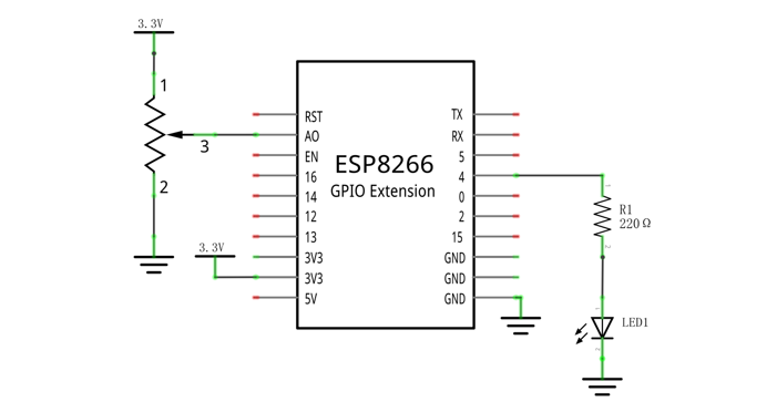
Use pin A0 on control board to detect the voltage of rotary potentiometer, and use pin 4 to control one LED.
Schematic diagram |
|
Hardware connection. If you need any support, please feel free to contact us via: support@freenove.com |
|
Code
Move the program folder “Freenove_Ultimate_Starter_Kit_for_ESP8266/Python/Python_Codes” to disk(D) in advance with the path of “D:/Micropython_Codes”.
Open “Thonny”, click “This computer” -> “D:” -> “Micropython_Codes” -> “10.1_Soft_LED” and double click “Soft_LED.py”.
10.1_Soft_LED
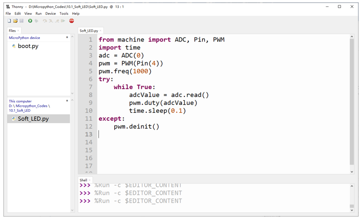
Click “Run current script”.Rotate the handle of potentiometer and the brightness of LED will change correspondingly.
The following is the code:
 1from machine import ADC, Pin, PWM
 2import time
 3adc = ADC(0)
 4pwm = PWM(Pin(4))
 5pwm.freq(1000)
 6try:
 7    while True:
 8        adcValue = adc.read()
 9        pwm.duty(adcValue)
10        time.sleep(0.1)
11except:
12    pwm.deinit()
In the code, read the ADC value of potentiometer and map it to the duty cycle of PWM to control LED brightness.
Project 10.2 Color Light
In this project, a potentiometer is used to control the RGB LED. The RGB LED is bright red when the potentiometer is near the midpoint, green when the potentiometer rotates to the “left” and blue when the potentiometer rotates to the “right”.
Component List
ESP8266 x1
|
USB cable
|
Breadboard x1
|
|
Rotary potentiometer x1
|
Jumper wire M/M x9 |
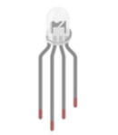
RGBLED x1
|
Resistor 220Ω x3 |
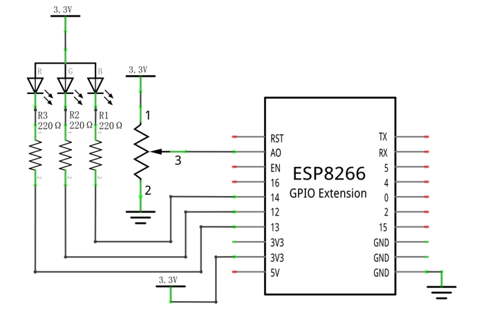
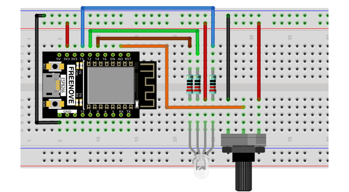
Circuit
Schematic diagram |
|
Hardware connection. If you need any support, please feel free to contact us via: support@freenove.com |
|
Code
Open “Thonny”, click “This computer” -> “D:” -> “Micropython_Codes” -> “10.2_Color_Light” and double click “Color_Light.py”.
10.2_Color_Light
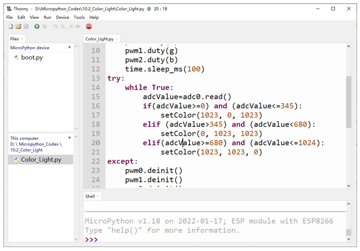
Download the code to ESP8266, rotate the potentiometers, then the color of RGB LED will change.
The following is the program code:
 1from machine import Pin,PWM,ADC
 2import time
 3
 4pwm0=PWM(Pin(13,Pin.OUT),1000)
 5pwm1=PWM(Pin(14,Pin.OUT),1000)
 6pwm2=PWM(Pin(12,Pin.OUT),1000)
 7adc0=ADC(0)
 8def setColor(r, g, b):
 9    pwm0.duty(r)
10    pwm1.duty(g)
11    pwm2.duty(b)
12    time.sleep_ms(100)
13try:
14    while True:
15        adcValue=adc0.read()
16
17        if(adcValue>=0) and (adcValue<=345):
18            setColor(1023, 0, 1023)
19        elif (adcValue>345) and (adcValue<680):
20            setColor(0, 1023, 1023)
21        elif(adcValue>=680) and (adcValue<=1024):
22            setColor(1023, 1023, 0)
23except:
24    pwm0.deinit()
25    pwm1.deinit()
26    pwm2.deinit()
In the code, you can read the potentiometer ADC value, judge the range of ADC value, to control the RGB LED color.
Project 10.3 Soft Rainbow Light
In this project, we use potentiometer to control Freenove 8 RGB LED Module.
Component List
ESP8266 x1
|
USB cable
|
|
Breadboard x1
|
||
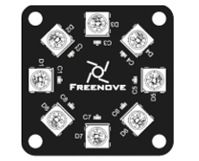
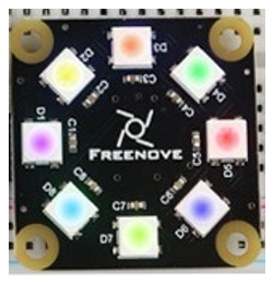
Freenove 8 RGB LED Module x1
|
Rotary potentiometer x1
|
Jumper wire F/M x3 Jumper wire M/M x7
|
Circuit
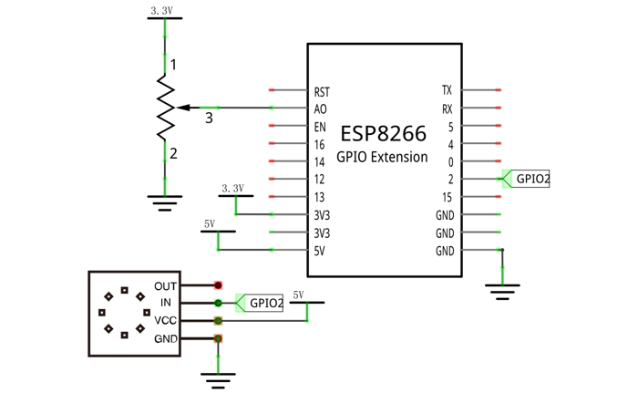
Use pin A0 on the control board to detect the voltage of rotary potentiometer.
Schematic diagram |
|
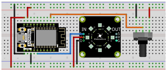
Hardware connection. If you need any support, please feel free to contact us via: support@freenove.com |
|
Code
Open “Thonny”, click “This computer” -> “D:” -> “Micropython_Codes” -> “10.3_Soft_Rainbow_Light” and double click “Soft_Rainbow_Light.py”.
10.3_Soft_Rainbow_Light
Click “Run current script”. Rotate the handle of potentiometer and the color of the lights will change.
If you have any concerns, please contact us via: support@freenove.com
The following is the program code:
 1from machine import Pin,ADC
 2import neopixel
 3import time
 4
 5np = neopixel.NeoPixel(Pin(2, Pin.OUT), 8)
 6
 7brightness=0.1         #brightbess
 8red=0                  #red
 9green=0                #green
10blue=0                 #blue
11
12adc = ADC(0)
13
14def wheel(pos):
15    global red,green,blue
16    WheelPos=pos%255
17    if WheelPos<85:
18        red=(255-WheelPos*3)
19        green=(WheelPos*3)
20        blue=0
21    elif WheelPos>=85 and WheelPos<170:
22        WheelPos -= 85;
23        red=0
24        green=(255-WheelPos*3)
25        blue=(WheelPos*3)
26    else :
27        WheelPos -= 170;
28        red=(WheelPos*3)
29        green=0
30        blue=(255-WheelPos*3)
31
32while True:
33        adcValue = adc.read()
34        for j in range(0,8):
35            wheel(adcValue/4+j*255//8)
36            np[j]=(int(red*brightness),int(green*brightness),int(blue*brightness))
37        np.write()
38        time.sleep_ms(10)
The logic of the code is basically the same as the previous project Rainbow Light. The difference is that in this code, the starting point of the color is controlled by the potentiometer.