Chapter 15 Motor & Driver
Project 15.1 Control Motor with Potentiometer
Control the direction and speed of the motor with a potentiometer.
Component List
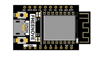
ESP8266 x1
|
USB cable |
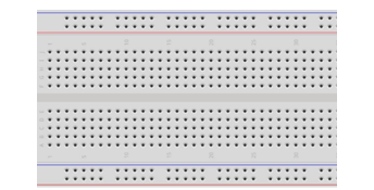
Breadboard x1
|
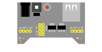
Breadboard Power module x1 |
Jumper wire M/M x12
|
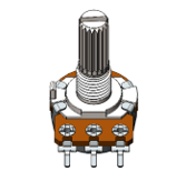
Rotary potentiometer x1 |
Motor x1
|
L293D |
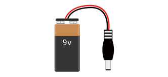
9V battery (prepared by yourself) & battery line
|
|


Component knowledge
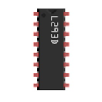
L293D
L293D is an IC chip (Integrated Circuit Chip) with a 4-channel motor drive. You can drive a unidirectional DC motor with 4 ports or a bi-directional DC motor with 2 ports or a stepper motor (stepper motors are covered later in this Tutorial).
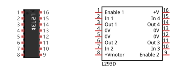
Port description of L293D module is as follows:
Pin name |
Pin number |
Description |
|---|---|---|
In x |
2, 7, 10, 15 |
Channel x digital signal input pin |
Out x |
3, 6, 11, 14 |
Channel x output pin, input high or low level according to In x pin, get connected to +Vmotor or 0V |
Enable1 |
1 |
Channel 1 and channel 2 enable pin, high level enable |
Enable2 |
9 |
Channel 3 and channel 4 enable pin, high level enable |
0V |
4, 5, 12, 13 |
Power cathode (GND) |
+V |
16 |
Positive electrode (VCC) of power supply, supply voltage 3.0~36V |
+Vmotor |
8 |
Positive electrode of load power supply, provide power supply for the Out pin x, the supply voltage is +V~36V |
For more detail, please refer to the datasheet for this IC Chip.
When using L293D to drive DC motor, there are usually two connection options.
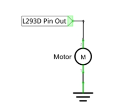
The following connection option uses one channel of the L239D, which can control motor speed through the PWM, However the motor then can only rotate in one direction.
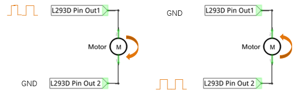
The following connection uses two channels of the L239D: one channel outputs the PWM wave, and the other channel connects to GND, therefore you can control the speed of the motor. When these two channel signals are exchanged, not only controls the speed of motor, but also can control the steering of the motor.
In practical use the motor is usually connected to channel 1 and 2 by outputting different levels to in1 and in2 to control the rotational direction of the motor, and output to the PWM wave to Enable1 port to control the motor’s rotational speed. If the motor is connected to channel 3 and 4 by outputting different levels to in3 and in4 to control the motor’s rotation direction, and output to the PWM wave to Enable2 pin to control the motor’s rotational speed.
Circuit
Use caution when connecting this circuit because the DC Motor is a high-power component. Do not use the power provided by the ESP8266 to power the motor directly, as this may cause permanent damage to your RPi! The logic circuit can be powered by the ESP8266’s power or an external power supply, which should share a common ground with ESP8266.
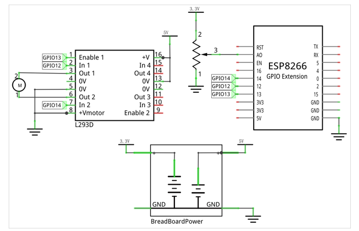
Schematic diagram |
|
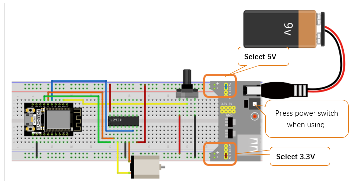
Hardware connection. If you need any support, please feel free to contact us via: support@freenove.com |
|
Code
Move the program folder “Freenove_Ultimate_Starter_Kit_for_ESP8266/Python/Python_Codes” to disk(D) in advance with the path of “D:/Micropython_Codes”.
Open “Thonny”, click “This computer” -> “D:” -> “Micropython_Codes” -> “15.1_Motor_And_Driver” and double click “Motor_And_Driver.py”.
15.1_Motor_And_Driver
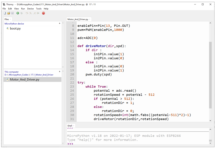
Click “Run current script”, rotate the potentiometer in one direction and the motor speeds up slowly in one direction. Rotate the potentiometer in the other direction and the motor will slow down to stop. And then rotate it in the original direction to accelerate the motor.
The following is the Code:
 1from machine import ADC,Pin,PWM
 2import time
 3import math
 4
 5in1Pin=Pin(12, Pin.OUT)
 6in2Pin=Pin(14, Pin.OUT)
 7
 8enablePin=Pin(13, Pin.OUT)
 9pwm=PWM(enablePin,1000)
10adc=ADC(0)
11
12def driveMotor(dir,spd):
13    if dir :
14        in1Pin.value(1)
15        in2Pin.value(0)
16    else :
17        in1Pin.value(0)
18        in2Pin.value(1)
19    pwm.duty(spd)
20
21try:
22    while True:
23        potenVal = adc.read()
24        rotationSpeed = potenVal - 512
25        if (potenVal > 512):
26            rotationDir = 1;
27        else:
28            rotationDir = 0;
29        rotationSpeed=int(math.fabs((potenVal-511)*2)-1)
30        driveMotor(rotationDir,rotationSpeed)
31        time.sleep_ms(10)
32except:
33    pass
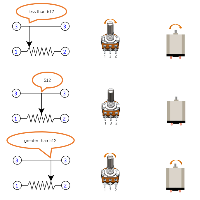
The ADC of ESP8266 has a 10-bit accuracy, corresponding to a range from 0 to 1023. In this program, set the number 512 as the midpoint. If the value of ADC is less than 512, make the motor rotate in one direction. If the value of ADC is greater than 512, make the motor rotate in the other direction. Subtract 512 from the ADC value and take the absolute value, and then divide this result by 2 to be the speed of the motor.
1potenVal = adc.read()
2rotationSpeed = potenVal - 512
3if (potenVal > 512):
4    rotationDir = 1;
5else:
6    rotationDir = 0;
7rotationSpeed=int(math.fabs((potenVal-511)*2)-1)
8driveMotor(rotationDir,rotationSpeed)
9time.sleep_ms(10)
Initialize pins of L293D chip.
1in1Pin=Pin(12, Pin.OUT)
2in2Pin=Pin(14, Pin.OUT)
3
4enablePin=Pin(13, Pin.OUT)
5pwm=PWM(enablePin,1000)
Initialize ADC pins, set the range of voltage to 0-3.3V and the acquisition width of data to 0-1023.
1adc=ADC(0)
Function driveMotor is used to control the rotation direction and speed of the motor. The dir represents direction while spd refers to speed.
1def driveMotor(dir,spd):
2    if dir :
3        in1Pin.value(1)
4        in2Pin.value(0)
5    else :
6        in1Pin.value(0)
7        in2Pin.value(1)
8    pwm.duty(spd)