17. Chapter Acceleration sensor
In the previous chapter, we have learned sensors that are used to detect light or temperature. Now we will learn a sensor that can detect acceleration.
17.1. Project Acceleration Detection
We will use serial port to get the data of MPU6050 module.
17.1.1. Component List
Control board x1
|
||
Breadboard x1
|
GPIO Extension Board x1
|
|
USB cable x1
|
Jumper M/M x4
|
|
Joystick x1
|
||


17.1.2. Component Knowledge
17.1.2.1. I2C communication
I2C (Inter-Integrated Circuit) is a two-wire serial communication mode, which can be used to the connection of micro controller and its peripheral equipment. Devices using I2C communication must be connected to the serial data (SDA) line, and serial clock (SCL) line (called I2C bus). Each device has a unique address and can be used as a transmitter or receiver to communicate with devices connected to the bus.
17.1.2.2. MPU6050
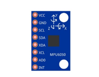
MPU6050 Sensor Module is a complete 6-axis Motion Tracking Device. It combines a 3-axis Gyroscope, a 3-axis Accelerometer and a DMP (Digital Motion Processor) all in a small package. The settings of the Accelerometer and Gyroscope of MPU6050 can be changed. A precision wide range digital temperature sensor is also integrated to compensate data readings for changes in temperature, and temperature values can also be read. The MPU6050 Module follows the I2C communication protocol and the default address is 0x68.
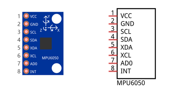
The port description of the MPU6050 module is as follows:
Pin name |
Pin number |
Description |
|---|---|---|
VCC |
1 |
Positive pole of power supply with voltage 5V |
GND |
2 |
Negative pole of power supply |
SCL |
3 |
I2C communication clock pin |
SDA |
4 |
I2C communication data pin |
XDA |
5 |
I2C host data pin which can be connected to other devices. |
XCL |
6 |
I2C host clock pin which can be connected to other devices. |
AD0 |
7 |
I2C address bit control pin. Low level: the device address is 0x68 High level: the device address is 0x69 |
INT |
8 |
Output interrupt pin |
For more detail, please refer to datasheet.
MPU6050 is widely used to assist with balancing vehicles, robots and aircraft, mobile phones and other products which require stability to control stability and attitude or which need to sense same.
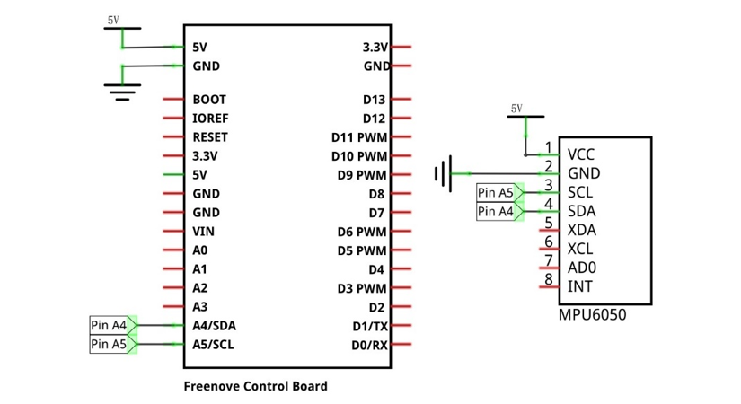
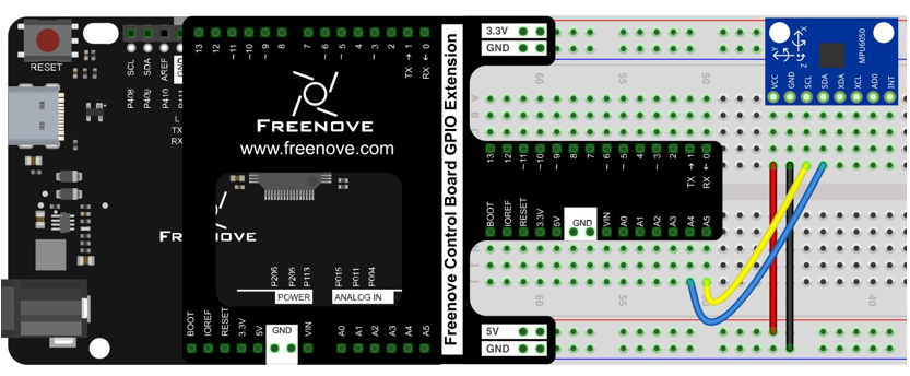
17.1.3. Circuit
Use pin A4/SDA, pin A5/SCL port on the control board to communicate with MPU6050 module.
Schematic diagram |
|
Hardware connection If you need any support, please feel free to contact us via: support@freenove.com |
|
17.1.4. Sketch
17.1.4.1. Sketch Acceleration_Detection
As we use the I2C interface to read the gyrpscope’s data, we need to install the related library before use.
Open Arduino IDE, click “Sketch” -> “Include Library” -> “Add.ZIP Library…”
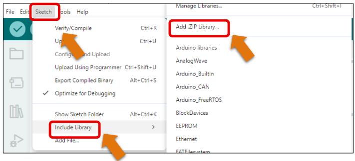
Click “Libraries”, then select “IMU_Fusion_SYC_v1.2.1.zip”.
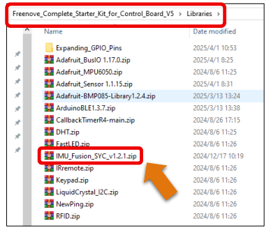
Or, you can search Adafruit_MPU6050 on library manager to install.
Now write sketch to communicate with the MPU6050 module and send the collected data to Serial Monitor window
 1/**********************************************************************
 2  Filename    : Sketch_17.1.1_Acceleration_Detection
 3  Description : Acceleration Detection
 4  Auther      : www.freenove.com
 5  Modification: 2024/08/05
 6**********************************************************************/
 7
 8#include "IMU_Fusion_SYC.h"
 9
10IMU imu(Wire);
11
12void setup() {
13  // put your setup code here, to run once:
14  Serial.begin(9600);// Set baud rate
15  Wire.begin();
16  imu.begin(CHOOSE_MPU6050);// IMU initialization
17  imu.MPU6050_CalcGyroOffsets();// MPU6050 calibration
18}
19
20void loop() {
21  // put your main code here, to run repeatedly:
22  imu.Calculate();// calculating data
23  Serial.println("\n****************************************************\n");
24  // Calculated data Output accelerometer and gyroscope data
25  Serial.print("accx:");
26  Serial.print(imu.getaccx());
27  Serial.print("\t");
28  Serial.print("accy:");
29  Serial.print(imu.getaccy());
30  Serial.print("\t");
31  Serial.print("accz:");
32  Serial.println(imu.getaccz());
33
34  Serial.print("gyrox:");
35  Serial.print(imu.getgyrox());
36  Serial.print("\t");
37  Serial.print("gyroy:");
38  Serial.print(imu.getgyroy());
39  Serial.print("\t");
40  Serial.print("gyroz:");
41  Serial.println(imu.getgyroz());
42  Serial.println("\n****************************************************\n");
43  delay(1000);
44}
Include the necessary libraries.
1#include "IMU_Fusion_SYC.h"
Initialize the sensor object. The IMU_Fusion_SYC library provides the IMU class to operate the MPU6050.
Before using it, you need to instantiate an object of the class.
1IMU imu(Wire);
MPU6050 initialization.
1imu.begin(CHOOSE_MPU6050);// IMU initialization
MPU6050 self-calibration.
1imu.MPU6050_CalcGyroOffsets();// MPU6050 calibration
Read acceleration, gyroscope from the MPU6050 and print them to the serial monitor
 1imu.Calculate();// calculating data
 2Serial.println("\n****************************************************\n");
 3// Calculated data Output accelerometer and gyroscope data
 4Serial.print("accx:");
 5Serial.print(imu.getaccx());
 6Serial.print("\t");
 7Serial.print("accy:");
 8Serial.print(imu.getaccy());
 9Serial.print("\t");
10Serial.print("accz:");
11Serial.println(imu.getaccz());
12
13Serial.print("gyrox:");
14Serial.print(imu.getgyrox());
15Serial.print("\t");
16Serial.print("gyroy:");
17Serial.print(imu.getgyroy());
18Serial.print("\t");
19Serial.print("gyroz:");
20Serial.println(imu.getgyroz());
21Serial.println("\n****************************************************\n");
22delay(1000);
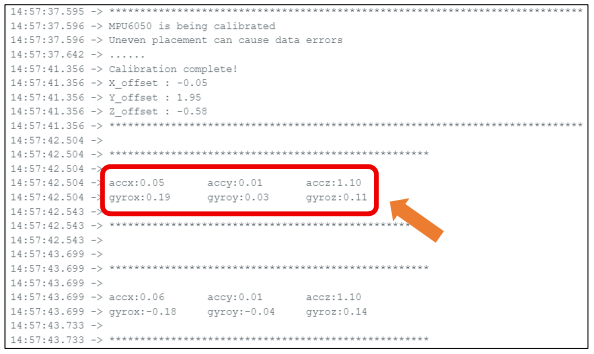
Verify and upload the code, open the Serial Monitor, then you can see the value of MPU6050 in original state and converted state, which is sent from control board. Rotate and move the MPU6050 module, and then you can see the change of values.
If you are unfamiliar with accelerometer and gyroscope data, the readings may not be immediately intuitive.
For better visualization, you can upload Sketch 17.1.2, which provides real-time angle outputs for all three axes.
Troubleshooting Tip: If the MPU6050 module fails to initialize (as shown in the image below), try the following steps:
1. Reconnect the USB cable - Unplug and replug it securely.
2. Check jumper wire connections - Ensure all jumper wires are firmly seated and well contacted.