1. Chapter LED Blink
We have previously tried to make the LED marked with “L” blink on the control board. Now let us use electronic components and codes to reproduce the phenomenon, and try to understand their principle.
1.1. Project Control LED with Manual Button
First, try using a push button switch to make the LED blink manually.
1.1.1. Component List
Note
It is worth noting that the board is compatible with the Arduino UNO R4 Minima and the Arduino UNO R4 WiFi board, and if you have one of them in hand, you can also use it for experiments in this tutorial.
Only the black control board is used to display the hardware connection in this document.
Control board x1
|
||
Breadboard x1
|
||
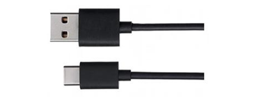
USB cable x1
|
Jumper M/M x2
|
|
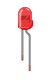
LED x1
|
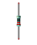
Resistor 220Ω x1
|
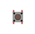
Push button x1
|


1.1.2. Circuit Knowledge
1.1.2.1. Power supply
Power supply provides energy for the circuit, and it is divided into DC power and AC power.
Voltage and current of DC power supply remains the same all the time, such as battery, power adapter.
Alternating Current (AC) describes the flow of charge that changes direction periodically. As a result, the voltage level also reverses along with the current. Its basic form is sinusoidal voltage(current). AC power is suitable for long-distance transmission of electric energy and it is used to supply power to houses.
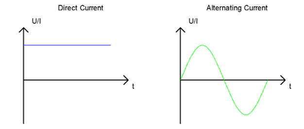
Generally, electronic circuits use DC. Home appliances have rectifiers to convert AC into DC before they are used.
Battery or battery pack can be represented by the following symbols:

The positive and negative poles of the power supply must not be directly connected, otherwise it may scald you and cause damage to the battery.
1.1.2.2. Voltage
The unit of voltage(U) is volt(V). 1kV=1000V, 1V=1000mV, 1mV=1000μv.
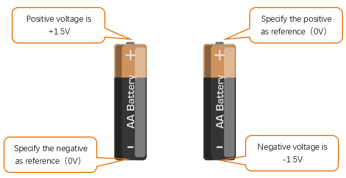
Voltage is relative. As to a dry battery marked with “1.5V”, it’s positive (+) voltage is 1.5V higher than the negative (-) voltage. If you specify the negative as reference(0V), the positive voltage will be +1.5V.
When two dry batteries are connected in series, the voltage of each point is as follows:
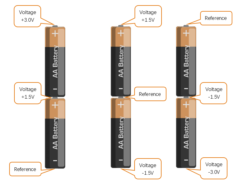
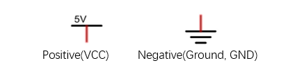
In practical circuits, we usually specify negative as reference voltage (0V), which is called “Ground”. The positive is usually called “VCC”. The positive and negative poles of power supply is usually represented by the following two symbols:
1.1.2.3. Current
The unit of current(I) is ampere(A). 1A=1000mA, 1mA=1000μA.
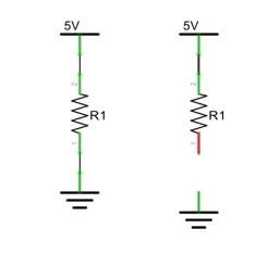
Closed loop consisting of electronic components is necessary for current to flow.
In the figures below: the left one is a loop circuit, so current flows through the circuit. The right one is not a loop circuit, so there is no current.
1.1.2.4. Resistor
Resistors use Ohms (Ω) as the unit of measurement of their resistance (R). 1MΩ=1000kΩ, 1kΩ=1000Ω.
A resistor is a passive electrical component that limits or regulates the flow of current in an electronic circuit.
On the left, we see a physical representation of a resistor, and the right is the symbol used to represent the presence of a resistor in a circuit diagram or schematic.
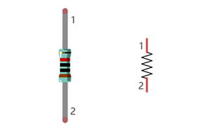
The bands of color on a resistor is a shorthand code used to identify its resistance value. For more details of resistor color codes, please refer to the card in the kit package.
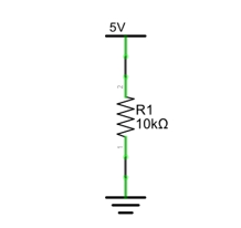
With a fixed voltage, there will be less current output with greater resistance added to the circuit. The relationship between Current, Voltage and Resistance can be expressed by this formula: I=V/R known as Ohm’s Law where I = Current, V = Voltage and R = Resistance. Knowing the values of any two of these allows you to solve the value of the third.
In the following diagram, the current through R1 is: I=U/R=5V/10kΩ=0.0005A=0.5mA.
Warning
Never connect the two poles of a power supply with anything of low resistance value (i.e. a metal object or bare wire) this is a Short and results in high current that may damage the power supply and electronic components.
1.1.3. Component Knowledge
Let us learn about the basic features of components to use them better.
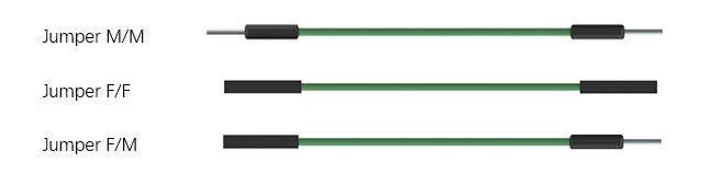
1.1.3.1. Jumper
Jumper is a kind of wire designed to connect the components together with its two terminals by inserting them onto breadboard or control board.
Jumpers have male end (pin) and female end (slot), so jumpers can be divided into the following 3 types.
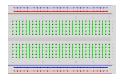
1.1.3.2. Breadboard
There are many small holes on breadboard to connect Jumpers.
Some small holes are connected inside breadboard. The following figure shows the inner links among those holes.
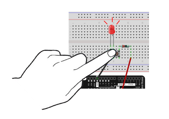
1.1.3.3. Push Button Switch
This type of Push Button Switch has 4 pins (2 Pole Switch). Two pins on the left are connected, and both left
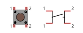
and right sides are the same per the illustration:
When the button on the switch is pressed, the circuit is completed (your project is Powered ON).
1.1.3.4. LED
An LED is a type of diode. All diodes only work if current is flowing in the correct direction and have two Poles. An LED will only work (light up) if the longer pin (+) of LED is connected to the positive output from a power source and the shorter pin is connected to the negative (-) negative output also referred to as Ground (GND). This type of component is known as “Polar” (think One-Way Street).
All common 2 lead diodes are the same in this respect. Diodes work only if the voltage of its positive electrode is higher than its negative electrode and there is a narrow range of operating voltage for most all common diodes of 1.9 and 3.4V. If you use much more than 3.3V the LED will be damaged and burn out.
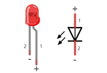
Note
LEDs cannot be directly connected to a power supply, which usually ends in a damaged component. A resistor with a specified resistance value must be connected in series to the LED you plan to use.
1.1.4. Circuit
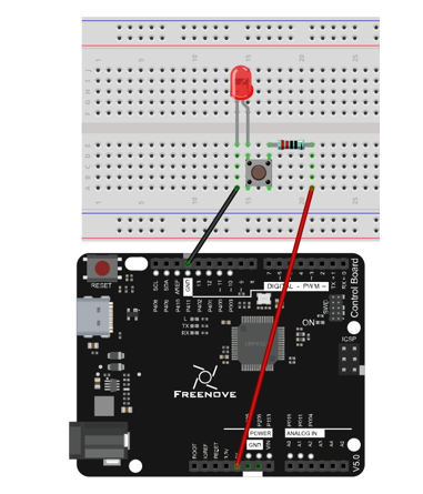
In this project, the LED is controlled by a push button switch, and the control board here only plays the role of power supply in the circuit.
Firstly, connect components with jumpers according to “hardware connection”. Secondly, check the connection to confirm that there are no mistakes. Finally, connect the control board to computer with USB cable to avoid short circuit caused by contacting the wires.
Note
In this book, we use the regular board as an example to make the circuits. The connection is the same on the control board with WiFi function.
Schematic diagram |
Hardware connection |
|
|
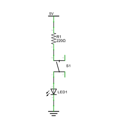
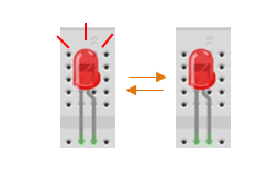
LED lights up when you press the push button switch, and it lights off when you release the button.
1.2. Project Control LED with Control Board
Now, try using control board to make LED blink through programing.
1.2.1. Component List
Components are basically the same with those in last section. Push button switch is no more needed.
1.2.2. Circuit Knowledge
1.2.2.1. Analog signal and Digital signal
An Analog Signal is a continuous signal in both time and value. On the contrary, a Digital Signal or discrete-time signal is a time series consisting of a sequence of quantities. Most signals in life are analog signals. A familiar example of an Analog Signal would be how the temperature throughout the day is continuously changing and could not suddenly change instantaneously from 0℃ to 10℃.
However, Digital Signals can instantaneously change in value. This change is expressed in numbers as 1 and 0 (the basis of binary code). Their differences can more easily be seen when compared when graphed as below.
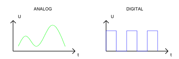
In practical applications, we often use binary as the digital signal, that is a series of 0’s and 1’s. Since a binary signal only has two values (0 or 1) it has great stability and reliability. Lastly, both analog and digital signals can be converted into the other.
1.2.2.2. Low level and high level
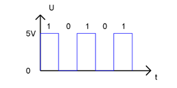
In a circuit, the form of binary (0 and 1) is presented as low level and high level.
Low level is generally equal to ground voltage(0V). High level is generally equal to the operating voltage of components.
The low level of the control board is 0V and high level is 5V, as shown below. When IO port on control board outputs high level, components of small power can be directly lit, like LED.
1.2.3. Code Knowledge
Before start writing code, we should learn about the basic programming knowledge.
1.2.3.2. Data type
When programming, we often use digital, characters and other data. C language has several basic data types as follows:
int: A number that does not have a fractional part, an integer, such as 0, 12, -1;
float: A number that has a fractional part, such as 0.1, -1.2;
char: It means character, such as ‘a’, ‘@’, ‘0’;
For more about date types, please visit the website: https://www.Arduino.cc-Resources-Reference-Data Types.
1.2.3.3. Constant
A constant is a kind of data that cannot be changed, such as int type 0, 1, float type 0.1, -0.1, char type ‘a’, ‘B’.
1.2.3.4. Variable
A variable is a kind of data that can be changed. It consists of a name, a value, and a type. Variables need to be defined before using, such as:
1int i;
“int” indicates the type, “;” indicates the end of the statement. The statement is usually written in one single line; and these statements form the code.
After declaration of the variable, you can use it. The following is an assignment to a variable:
1i = 0; // after the execution, the value of i is 0
“=” is used to pass the value of a variable or constant on the right side to the variable on the left.
A certain number of variables can be declared in one statement, and a variable can be assigned multiple times. Also, the value of a variable can be passed to other variables. For example:
1int i, j;
2i = 0;                    // after the execution, the value of i is 0
3i = 1;                    // after the execution, the value of i is 1
4j = i;                    // after the execution, the value of j is 1
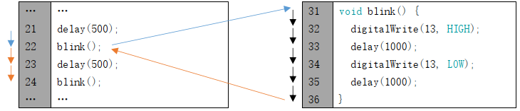
1.2.3.5. Function
A function is a collection of statements with a sequence of order, which performs a defined task. Let’s define a function void blink() as follows:
1void blink() {
2    digitalWrite(13, HIGH);
3    delay(1000);
4    digitalWrite(13, LOW);
5    delay(1000);
6}
“void” indicates that the function does not return a value (Chapter 4 will detail the return value of functions);
“()” its inside is parameters of a function (Chapter 2 will detail the parameters of the functions). No content inside it indicates that this function has no parameters;
“{}” contains the entire code of the function.
After the function is defined, it is necessary to be called before it is executed. Let’s call the function void blink(), as shown below.
blink();
When the code is executed to a statement calling the function, the function will be executed. After execution of the function is finished, it will go back to the statement and execute the next statement.
Some functions have one or more parameters. When you call such functions, you need to write parameters inside “()”:
1digitalWrite(13, HIGH);   // turn the LED on (HIGH is the voltage level)
2delay(1000);              // wait for a second
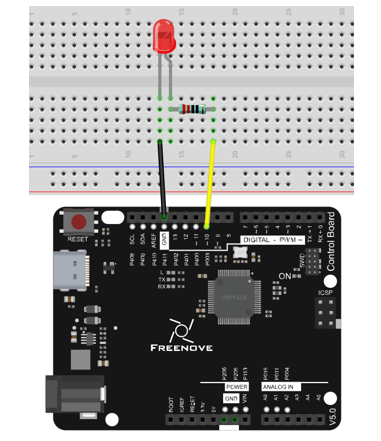
1.2.4. Circuit
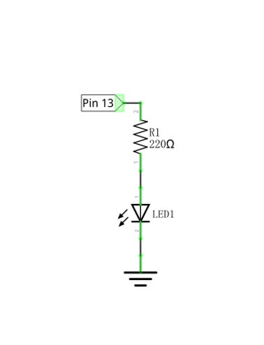
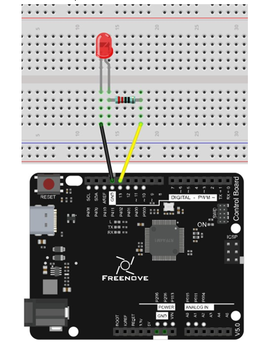
Now, we will use IO port of control board to provide power for the LED. Pin 13 of the control board is the digital pin. It can output high level or low level. In this way, control board can control the state of LED.
Schematic diagram |
Hardware connection |
|
|
1.2.5. Sketch
1.2.5.1. Sketch Control_LED_by_Control_Board
In order to make the LED blink, we need to make pin 13 of the control board output high and low level alternately.
We highly recommend you type the code manually instead of copying and pasting, so that you can develop your coding skills and get more knowledge.
 1/**********************************************************************
 2  Filename    : Sketch_1.2.1_Control_LED_by_Control_Board
 3  Description : Control LED by Control Board
 4  Auther      : www.freenove.com
 5  Modification: 2024/08/05
 6**********************************************************************/
 7
 8// the setup function runs once when you press reset or power the board
 9void setup() {
10  // initialize digital pin 13 as an output
11  pinMode(13, OUTPUT);
12}
13
14// the loop function runs over and over again forever
15void loop() {
16  digitalWrite(13, HIGH);   // turn the LED on (HIGH is the voltage level)
17  delay(1000);              // wait for a second
18  digitalWrite(13, LOW);    // turn the LED off by making the voltage LOW
19  delay(1000);              // wait for a second
20}
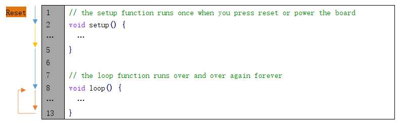
The code usually contains two basic functions: void setup() and void loop().
After control board is reset , the setup() function will be executed first, and then the loop() function will be executed.
setup() function is generally used to write code to initialize the hardware. And loop() function is used to write code to achieve certain functions. loop() function is executed repeatedly. When the execution reaches the end of loop(), it will jump to the beginning of loop() to run again.
- Reset()
Reset operation will lead the code to be executed from the beginning. Switching on the power, finishing uploading the code and pressing the reset button will trigger reset operation.
In the setup () function, first, we set pin 13 of the control board as output mode, which can make the port output high level or low level.
1// initialize digital pin 13 as an output
2pinMode(13, OUTPUT);
Then, in the loop () function, set pin 13 of the control board to output high level to make LED light up.
1digitalWrite(13, HIGH); // turn the LED on (HIGH is the voltage level)
Wait for 1000ms, which is 1s. delay() function is used to make control board wait for a moment before executing the next statement. The parameter indicates the number of milliseconds to wait for.
1delay(1000); // wait for a second
Then set the 13 pint to output low level, and LED light off. One second later, the execution of loop () function will be completed.
1digitalWrite(13, LOW);    // turn the LED off by making the voltage LOW
2delay(1000);              // wait for a second
The loop() function is constantly being executed, so LED will keep blinking.
The functions called above are standard functions of the Arduino IDE, which have been defined in the Arduino IDE, and they can be called directly. We will introduce more common standard functions in later chapters.
For more standard functions and the specific use method, please visit https://www.arduino.cc-Resources-Reference-Functions.
Verify and upload the code, then the LED starts blinking.
1.3. How to Use the Expanding GPIO Pins
In this section, we will learn to use the expanding GPIO pins. If you are working on the board with Bluetooth and WiFi functions, you can skip this section.
The board used in this section is as shown below:
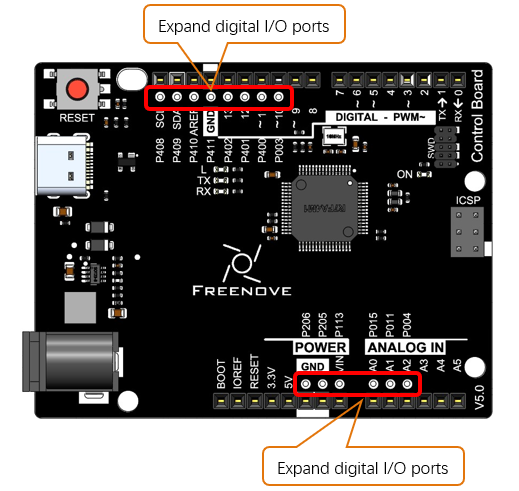
Before using the expanding GPIO pins, please complete the following configuration first.
Copy “pins_arduino.h” and “variant.cpp” under the file path “/Libraries/Expanding_GPIO_Pins” to the file path “C:\Users\Freenove\AppData\Local\Arduino15\pa ckages\arduino\hardware\renesas_uno\1.1.0\variants\MINIMA “.
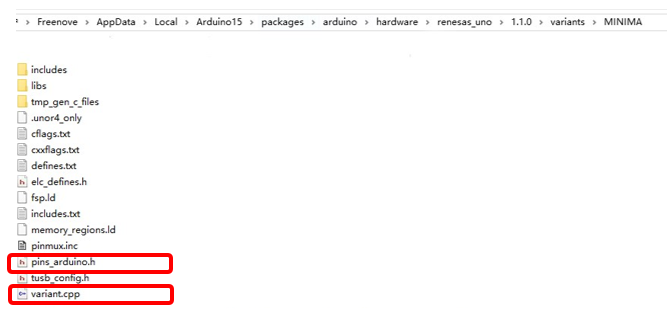
The path may vary due to different versions of board package installed.
The configuration is completed onve the files are copied the files to the above path. The definition of the expanding GPIOs is as shown in the table below.
GPIOs on the control board |
Definition of Arduino GPIO |
|---|---|
P003 |
D27 |
P400 |
D28 |
P401 |
D29 |
P402 |
D30 |
P411 |
D31 |
P410 |
D32 |
P409 |
D33 |
P408 |
D34 |
P004 |
D35 |
P011 |
D36 |
P015 |
D37 |
P113 |
D38 |
P205 |
D39 |
P206 |
D40 |
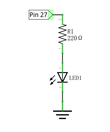
Now, let’s try to use the expanding GPIO pins to light up an LED. Open the Blinking sketch, modify the control pin according to the pin definition shown in the above table. Here we take P003 on the control board as an example, so we modify the control pin of the LED to 27.
Build the circuit as below, and upload the sketch to the board.
Schematic diagram |
Hardware connection |
|
|
 1// the setup function runs once when you press reset or power the board
 2void setup() {
 3    // initialize digital pin 13 as an output
 4    pinMode(27, OUTPUT);
 5}
 6
 7// the loop function runs over and over again forever
 8void loop() {
 9    digitalWrite(27, HIGH);   // turn the LED on (HIGH is the voltage level)
10    delay(1000);              // wait for a second
11    digitalWrite(27, LOW);    // turn the LED off by making the voltage LOW
12    delay(1000);              // wait for a second
13}
In this way, you can use more GPIOs to design more interesting projects. It is worth noting that all the expansion GPIOs are uniformly defined as ordinary digital I/O interfaces. We do not solder male or female headers to them. When you need to use these pins, you can solder headers yourself.
1.2.3.1. Comments
Comments are the words used to explain for the sketches, and they won’t affect the running of code.
There are two ways to use comments of sketches.
Symbol “//”
Contents behind “//” comment out the code in a single line.
The content in front of “//” will not be affected.
Symbol “/”and “/”
Code can also be commented out by the contents starting with a “/” and finishing with a “/” and you can place it anywhere in your code, on the same line or several lines.
Or