3. Chapter Buttons & LEDs
Usually, there are three essential parts in a complete automatic control device: INPUT, OUTPUT, and CONTROL. In last section, the LED module was the output part and RPI was the control part. In practical applications, we not only make LEDs flash, but also make a device sense the surrounding environment, receive instructions and then take the appropriate action such as turn on LEDs, make a buzzer beep and so on.

Next, we will build a simple control system to control an LED through a push button switch.
3.1. Project Push Button Switch & LED
In the project, we will control the LED state through a Push Button Switch. When the button is pressed, our LED will turn ON, and when it is released, the LED will turn OFF. This describes a Momentary Switch.
3.1.1. Component List
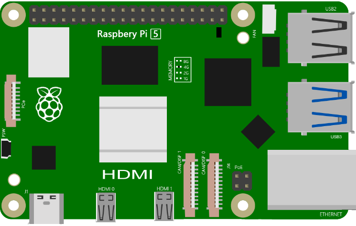
Raspberry Pi (Recommended: Raspberry Pi 5 / 4B / 3B+ / 3B) (Compatible: 3A+ / 2B / 1B+ / 1A+ / Zero W / Zero) |
|||
LED x1 |
Breadboard x1 |
||
GPIO Extension Board & Ribbon Cable |
|||
Push Button Switch x1 |
Resistor 10KΩ x2 |
Resistor 220Ω x1
|
|
Jumper (some) |
|||


Note
In the code “button” represents switch action.
3.1.2. Component knowledge
3.1.2.1. Push Button Switch
This type of Push Button Switch has 4 pins (2 Pole Switch). Two pins on the left are connected, and both left and right sides are the same per the illustration:
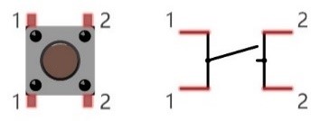
When the button on the switch is pressed, the circuit is completed (your project is Powered ON).
3.1.3. Circuit
Schematic diagram
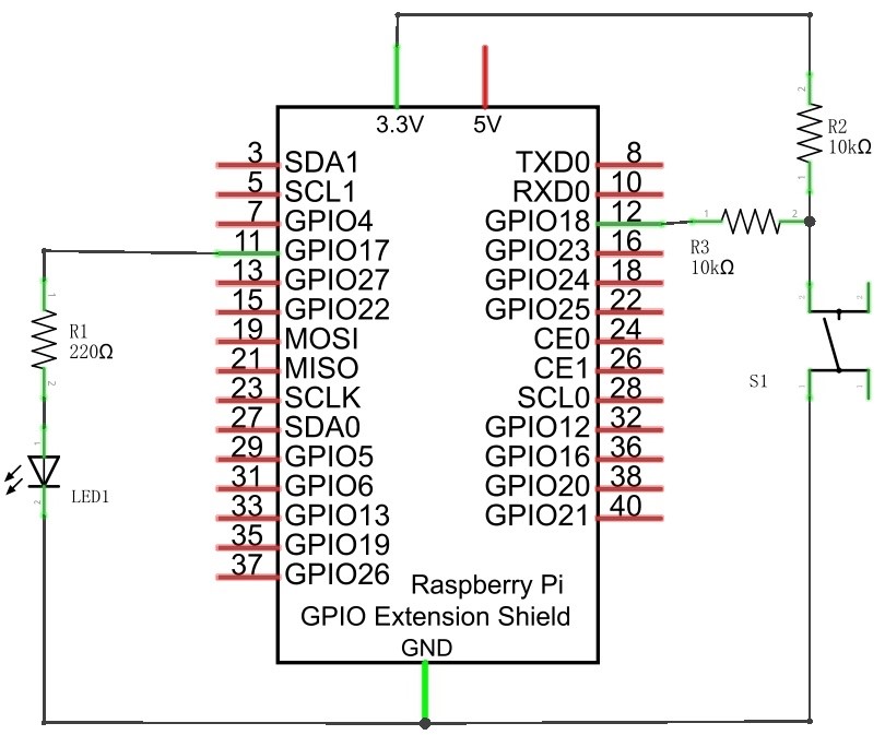
Note
R3 is used to limit current to protect GPIO 18, if you set it to output HIGH level by mistake.
Hardware connection

Hint
If you need any support, please feel free to contact us via: support@freenove.com
3.1.4. Sketch
In this chapter, we will introduce how to use the button to control the LED.
3.1.4.1. Sketch_03_ButtonLED
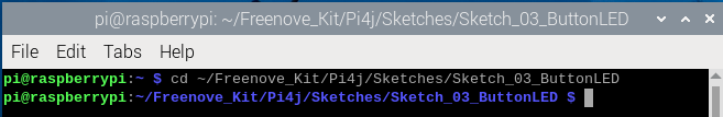
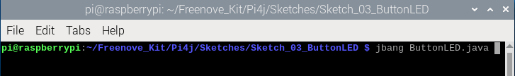
First, enter where the project is located:
$ cd ~/Freenove_Kit/Pi4j/Sketches/Sketch_03_ButtonLED
Enter the command to run the code.
$ jbang ButtonLED.java
When the code is running, press the button and you can see the LED is lit; release it and the LED goes off.
On the Raspberry Pi terminal, you will see the corresponding messages printed.
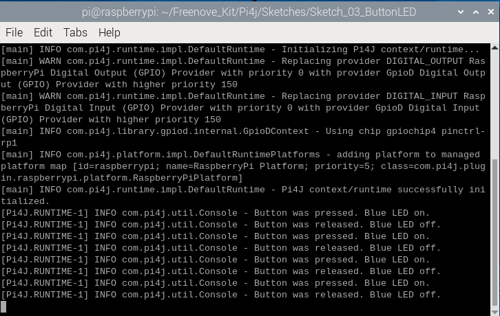
Press Ctrl+C to exit the code.
You can open the code with geany to view and edit it.
$ geany ButtonLED.java
Click the icon to run the code.
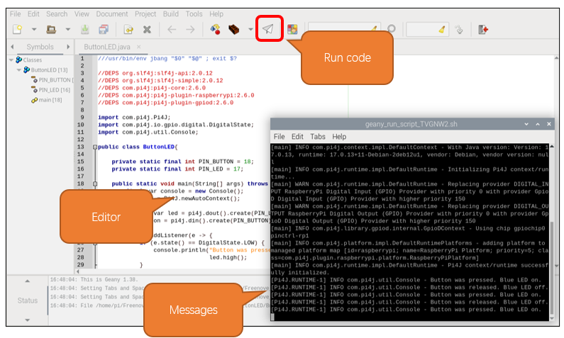
If the code fails to run, please check Geany Configuration.
The following is program code:
 1///usr/bin/env jbang "$0" "$@" ; exit $?
 2
 3//DEPS org.slf4j:slf4j-api:2.0.12
 4//DEPS org.slf4j:slf4j-simple:2.0.12
 5//DEPS com.pi4j:pi4j-core:2.6.0
 6//DEPS com.pi4j:pi4j-plugin-raspberrypi:2.6.0
 7//DEPS com.pi4j:pi4j-plugin-gpiod:2.6.0
 8
 9import com.pi4j.Pi4J;
10import com.pi4j.io.gpio.digital.DigitalState;
11import com.pi4j.util.Console;
12
13public class ButtonLED{
14
15    private static final int PIN_BUTTON = 18;
16    private static final int PIN_LED = 17;
17
18    public static void main(String[] args) throws Exception {
19        final var console = new Console();
20        var pi4j = Pi4J.newAutoContext();
21
22        var led = pi4j.dout().create(PIN_LED);
23        var button = pi4j.din().create(PIN_BUTTON);
24
25        button.addListener(e -> {
26            if (e.state() == DigitalState.LOW) {
27                console.println("Button was pressed. Blue LED on.");
28                led.high();
29            }
30            else if(e.state() == DigitalState.HIGH){
31                console.println("Button was released. Blue LED off.");
32                led.low();
33            }
34        });
35
36        try{
37            while (true) {
38                Thread.sleep(500);
39            }
40        }
41        finally{
42            pi4j.shutdown();
43        }
44    }
45}
Import the classes of Pi4J library for GPIO control and simple console output.
1import com.pi4j.Pi4J;
2import com.pi4j.io.gpio.digital.DigitalState;
3import com.pi4j.util.Console;
Define the GPIO numbers for the button and LED.
1private static final int PIN_BUTTON = 18;
2private static final int PIN_LED = 17;
Create a Console instance for printing logs or messages.
Create a Pi4J context to manage the GPIO interface.
Create an LED output pin object, connected to the pin specified by PIN_LED.
Create a button input pin object, connected to the pin specified by PIN_BUTTON.
1final var console = new Console();
2var pi4j = Pi4J.newAutoContext();
3
4var led = pi4j.dout().create(PIN_LED);
5var button = pi4j.din().create(PIN_BUTTON);
Add a listener event to the button, which is triggered when the button’s state changes.
When the button is pressed, its state is low, and we control the LED to light up.
When the button is released, its state is high, and we control the LED to turn off.
 1button.addListener(e -> {
 2    if (e.state() == DigitalState.LOW) {
 3        console.println("Button was pressed. Blue LED on.");
 4        led.high();
 5    }
 6    else if(e.state() == DigitalState.HIGH){
 7        console.println("Button was released. Blue LED off.");
 8        led.low();
 9    }
10});
Nothing needs to be done in the main loop. Just set it in an infinite loop and ensure that the Pi4J context is closed when the program ends.
1try{
2    while (true) {
3        Thread.sleep(500);
4    }
5}
6finally{
7    pi4j.shutdown();
8}