1. Chapter LED
This chapter is the Start Point in the journey to build and explore RPi electronic projects. We will start with simple “Blink” project.
1.1. Project Blink
In this project, we will use RPi to control blinking a common LED.
1.1.1. Component List
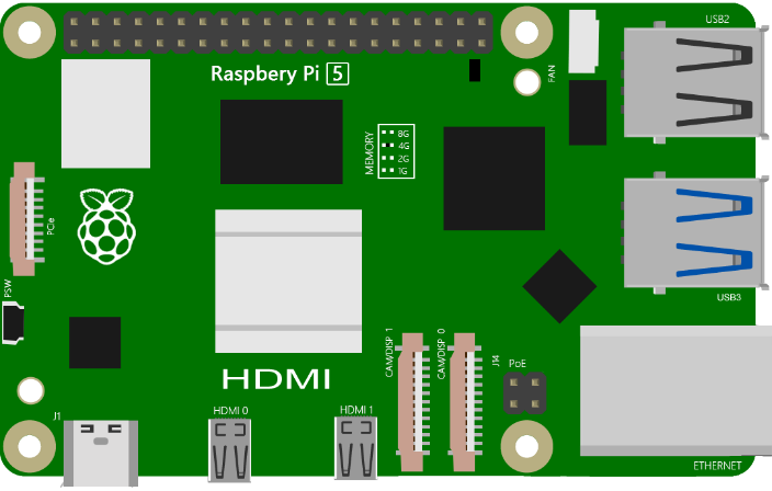
Raspberry Pi (Recommended: Raspberry Pi 5 / 4B / 3B+ / 3B) (Compatible: 3A+ / 2B / 1B+ / 1A+ / Zero W / Zero) |
||
Breadboard x1 |
||
GPIO Extension Board & Ribbon Cable |
Resistor 220Ω x1 |
|
Jumper Specific quantity depends on the circuit.
|
LED x1
|
|


In the components list, 3B GPIO, Extension Shield Raspberry and Breadboard are necessary for each project. Later, they will be reference by text only (no images as in above).
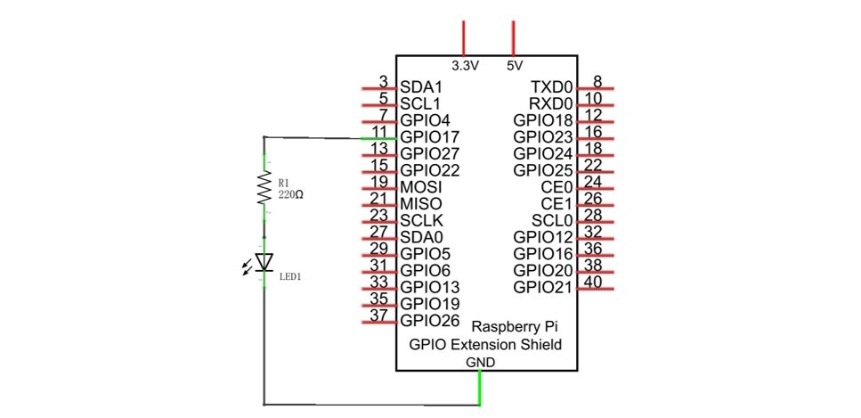
Schematic diagram
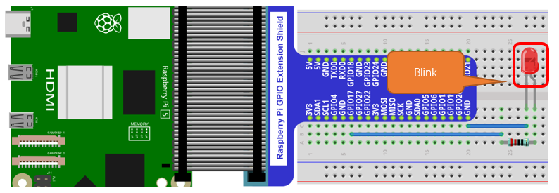
Hardware connection
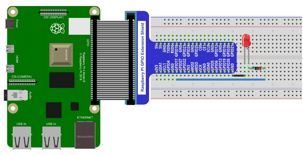
Because the numbering of the GPIO Extension Shield is the same as that of the RPi GPIO, future hardware connection diagrams will only show that part of breadboard and GPIO Extension Shield.
1.1.2. Component knowledge
1.1.2.1. LED
An LED is a type of diode. All diodes only work if current is flowing in the correct direction and have two Poles. An LED will only work (light up) if the longer pin (+) of LED is connected to the positive output from a power source and the shorter pin is connected to the negative (-) output, which is also referred to as Ground (GND). This type of component is known as “Polar” (think One-Way Street).
All common 2 lead diodes are the same in this respect. Diodes work only if the voltage of its positive electrode is higher than its negative electrode and there is a narrow range of operating voltage for most all common diodes of 1.9 and 3.4V. If you use much more than 3.3V the LED will be damaged and burnt out.

Note
Note: LEDs cannot be directly connected to a power supply, which usually ends in a damaged component. A resistor with a specified resistance value must be connected in series to the LED you plan to use.
1.1.2.2. Resistor
Resistors use Ohms (Ω) as the unit of measurement of their resistance (R). 1MΩ=1000kΩ, 1kΩ=1000Ω.
A resistor is a passive electrical component that limits or regulates the flow of current in an electronic circuit.
On the left, we see a physical representation of a resistor, and the right is the symbol used to represent the presence of a resistor in a circuit diagram or schematic.
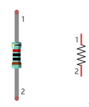
The bands of color on a resistor is a shorthand code used to identify its resistance value. For more details of resistor color codes, please refer to the card in the kit package.
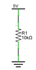
With a fixed voltage, there will be less current output with greater resistance added to the circuit. The relationship between Current, Voltage and Resistance can be expressed by this formula: I=V/R known as Ohm’s Law where I = Current, V = Voltage and R = Resistance. Knowing the values of any two of these allows you to solve the value of the third.
In the following diagram, the current through R1 is:
Warning
WARNING: Never connect the two poles of a power supply with anything of low resistance value (i.e. a metal object or bare wire) this is a Short and results in high current that may damage the power supply and electronic components.
Note
Note: Unlike LEDs and Diodes, Resistors have no poles and re non-polar (it does not matter which direction you insert them into a circuit, it will work the same)
1.1.2.3. Breadboard
Here we have a small breadboard as an example of how the rows of holes (sockets) are electrically attached. The left picture shows the ways the pins have shared electrical connection and the right picture shows the actual internal metal, which connect these rows electrically.


1.1.2.4. GPIO Extension Board
GPIO board is a convenient way to connect the RPi I/O ports to the breadboard directly. The GPIO pin sequence on Extension Board is identical to the GPIO pin sequence of RPi.

1.1.3. Sketch
According to the circuit, when the GPIO17 of Raspberry Pi output level is high, the LED turns ON. Conversely, when the GPIO17 Raspberry Pi output level is low, the LED turns OFF. Therefore, we can let GPIO17 cycle output high and output low level to make the LED blink.
1.1.3.1. Sketch_01_Blink
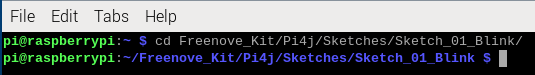
First, enter where the project is located:
$ cd ~/Freenove_Kit/Pi4j/Sketches/Sketch_01_Blink
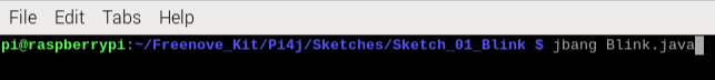
Enter the command to run the code.
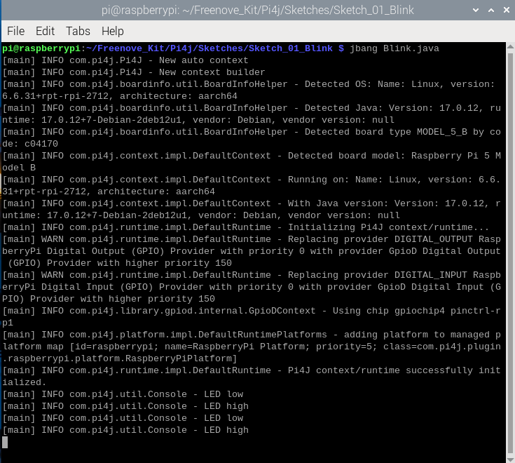
$ jbang Blink.java
Upon the code runs, you can see the onboard blue LED blinks.
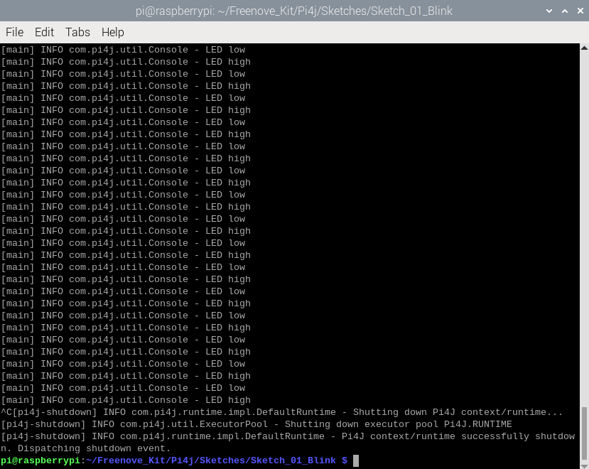
And on Raspberry Pi Terminal, you can see the corresponding messages printed.
Press CTRL-C to exit the program.
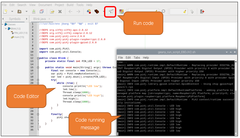
If you want to view or modify the code, you can open the code with Geany with the following command.
$ geany Blink.java
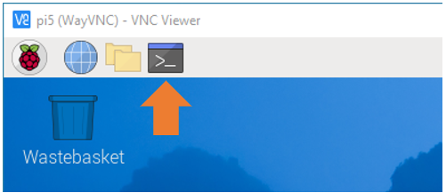
Click the icon to run the code.
If the code fails to run, please check Geany Configuration.
The following is program code:
 1///usr/bin/env jbang "$0" "$@" ; exit $?
 2
 3//DEPS org.slf4j:slf4j-api:2.0.12
 4//DEPS org.slf4j:slf4j-simple:2.0.12
 5//DEPS com.pi4j:pi4j-core:2.6.0
 6//DEPS com.pi4j:pi4j-plugin-raspberrypi:2.6.0
 7//DEPS com.pi4j:pi4j-plugin-gpiod:2.6.0
 8
 9import com.pi4j.Pi4J;
10import com.pi4j.util.Console;
11
12public class Blink {
13    private static final int PIN_LED = 17;
14
15    public static void main(String[] args) throws Exception {
16        final var console = new Console();
17        var pi4j = Pi4J.newAutoContext();
18        var led = pi4j.dout().create(PIN_LED);
19
20        try {
21            while (true) {
22                console.println("LED low");
23                led.low();
24                Thread.sleep(1000);
25                console.println("LED high");
26                led.high();
27                Thread.sleep(1000);
28            }
29        } finally {
30            pi4j.shutdown();
31        }
32    }
33}
At the beginning of the code, we use shebang command to inform Raspberry Pi that we are going to use JBangto run Java script.
1///usr/bin/env jbang "$0" "$@" ; exit $?
Likewise, we specify the dependencies required for the script to run. This includes the different components of the SLF4J logging library and the Pi4J library and their version numbers.
1//DEPS org.slf4j:slf4j-api:2.0.12
2//DEPS org.slf4j:slf4j-simple:2.0.12
3//DEPS com.pi4j:pi4j-core:2.6.0
4//DEPS com.pi4j:pi4j-plugin-raspberrypi:2.6.0
5//DEPS com.pi4j:pi4j-plugin-gpiod:2.6.0
Import Pi4J library and the Console class to facilitate creating and managing contexts and printing messages on the console.
1import com.pi4j.Pi4J;
2import com.pi4j.util.Console;
Assign the GPIO pin to the LED, and configure it as output mode.
1private static final int PIN_LED = 17;
2
3public static void main(String[] args) throws Exception {
4    final var console = new Console();
5    var pi4j = Pi4J.newAutoContext();
6    var led = pi4j.dout().create(PIN_LED);
Use the try…finally structure to ensure the smooth running of the code.
 1try {
 2    while (true) {
 3        console.println("LED low");
 4        led.low();
 5        Thread.sleep(1000);
 6        console.println("LED high");
 7        led.high();
 8        Thread.sleep(1000);
 9    }
10} finally {
11    pi4j.shutdown();
12}
Make the LED turn on and off once every 1 second, repeat this process, and print prompt messages.
1while (true) {
2    console.println("LED low");
3    led.low();
4    Thread.sleep(1000);
5    console.println("LED high");
6    led.high();
7    Thread.sleep(1000);
8}
1.1.4. Freenove Car, Robot and other products for Raspberry Pi
We also have car and robot kits for Raspberry Pi. You can visit our website for details.
https://www.amazon.com/freenove
FNK0043–Freenove 4WD Smart Car Kit for Raspberry Pi
FNK0050–Freenove Robot Dog Kit for Raspberry Pi
FNK0052–Freenove_Big_Hexapod_Robot_Kit_for_Raspberry_Pi