Logo

FNK0092

  • C language
    • Welcome
      • Getting Started
      • Get Support and Offer Input
      • Safety and Precautions
      • About Freenove
      • Copyright
    • Preface
      • Control Board
    • 0. Getting Ready (Important)
      • Programming Software
      • Installation of Development Board Support Package
      • First Use
      • How to install the library
    • 1. Chapter LED Blink
      • 1.1. Project Control LED with Manual Button
        • 1.1.1. Component List
        • 1.1.2. Circuit Knowledge
          • 1.1.2.1. Power supply
          • 1.1.2.2. Voltage
          • 1.1.2.3. Current
          • 1.1.2.4. Resistor
        • 1.1.3. Component Knowledge
          • 1.1.3.1. Jumper
          • 1.1.3.2. Breadboard
          • 1.1.3.3. Push Button Switch
          • 1.1.3.4. LED
        • 1.1.4. Circuit
      • 1.2. Project Control LED with Control Board
        • 1.2.1. Component List
        • 1.2.2. Circuit Knowledge
          • 1.2.2.1. Analog signal and Digital signal
          • 1.2.2.2. Low level and high level
        • 1.2.3. Code Knowledge
          • 1.2.3.1. Comments
          • 1.2.3.2. Data type
          • 1.2.3.3. Constant
          • 1.2.3.4. Variable
          • 1.2.3.5. Function
        • 1.2.4. Circuit
        • 1.2.5. Sketch
          • 1.2.5.1. Sketch Control_LED_by_Control_Board
            • Reset()
      • 1.3. How to Use the Expanding GPIO Pins
    • 2. Chapter Two LEDs Blink
      • 2.1. Project Two LEDs Blink
        • 2.1.1. Component List
        • 2.1.2. Code Knowledge
          • 2.1.2.1. Parameters of function
          • 2.1.2.2. Boolean data type
          • 2.1.2.3. Logical operator
          • 2.1.2.4. Relation operator
          • 2.1.2.5. Conditional statement
        • 2.1.3. Circuit
        • 2.1.4. Sketch
          • 2.1.4.1. Sketch Two_LEDs_Blink
          • 2.1.4.2. Sketch Two_LEDs_Blink
          • 2.1.4.3. Sketch Two_LEDs_Blink
    • 3. Chapter LED Bar Graph
      • 3.1. Project LED Bar Graph Display
        • 3.1.1. Component List
        • 3.1.2. Component Knowledge
          • 3.1.2.1. LED bar graph
        • 3.1.3. Code Knowledge
          • 3.1.3.1. Array
          • 3.1.3.2. Loop
        • 3.1.4. Circuit
        • 3.1.5. Sketch
          • 3.1.5.1. Sketch LED_bar_graph_Display
          • 3.1.5.2. Sketch LED_bar_graph_Display
    • 4. Chapter LED Blink Smoothly
      • 4.1. Project LEDs Emit Different Brightness
        • 4.1.1. Component List
        • 4.1.2. Circuit Knowledge
          • 4.1.2.1. PWM
        • 4.1.3. Code Knowledge
          • 4.1.3.1. Return value of function
          • 4.1.3.2. return
        • 4.1.4. Circuit
        • 4.1.5. Sketch
          • 4.1.5.1. Sketch LEDs_Emit_Different_Brightness
            • analogWrite()
            • map()
      • 4.2. Project LED Blinking Smoothly
        • 4.2.1. Component List
        • 4.2.2. Circuit
        • 4.2.3. Sketch
          • 4.2.3.1. Sketch LED_Blink_Smoothly
    • 5. Chapter Control LED with Push Button Switch
      • 5.1. Project Control LED with Push Button Switch
        • 5.1.1. Component List
        • 5.1.2. Circuit Knowledge
          • 5.1.2.1. Connection of Push Button Switch
        • 5.1.3. Circuit
        • 5.1.4. Sketch
          • 5.1.4.1. Sketch Control_LED_Through_Push_Button
            • digitalRead()
      • 5.2. Project Change LED State with Push Button Switch
        • 5.2.1. Component List
        • 5.2.2. Circuit Knowledge
          • 5.2.2.1. Debounce a push button switch
        • 5.2.3. Circuit
        • 5.2.4. Sketch
          • 5.2.4.1. Sketch Change_LED_State_by_Push_Button
    • 6. Chapter Serial
      • 6.1. Project Send Data through Serial
        • 6.1.1. Component List
        • 6.1.2. Code Knowledge
          • 6.1.2.1. Bit and Byte
        • 6.1.3. Circuit Knowledge
          • 6.1.3.1. Serial and parallel communication
          • 6.1.3.2. Serial communication
          • 6.1.3.3. Serial port on Control board
        • 6.1.4. Circuit
        • 6.1.5. Sketch
          • 6.1.5.1. Sketch Send_data_through_Serial
      • 6.2. Project Receive Data through Serial Port
        • 6.2.1. Component List
        • 6.2.2. Code Knowledge
          • 6.2.2.1. Interrupt
        • 6.2.3. Circuit
        • 6.2.4. Sketch
          • 6.2.4.1. Sketch Receive_Data_through_Serial_Port
      • 6.3. Project Application of Serial
        • 6.3.1. Component List
        • 6.3.2. Circuit
        • 6.3.3. Sketch
          • 6.3.3.1. Sketch Application_of_Serial
            • constrain()
    • 7. Chapter Timer
      • 7.1. Project Serial print using timer
        • 7.1.1. Component List
        • 7.1.2. Code Knowledge
          • 7.1.2.1. Timer
        • 7.1.3. Circuit
        • 7.1.4. Sketch
          • 7.1.4.1. How to install the library
          • 7.1.4.2. Sketch Serial_print_using_timer
      • 7.2. Project Using timer to implement LED blinking
        • 7.2.1. Component List
        • 7.2.2. Circuit
        • 7.2.3. Sketch
          • 7.2.3.1. Sketch Using_timer_to_implement_LED_blinking
    • 8. Chapter ADC
      • 8.1. Project ADC
        • 8.1.1. Component List
        • 8.1.2. Circuit Knowledge
          • 8.1.2.1. ADC
        • 8.1.3. Component Knowledge
          • 8.1.3.1. Potentiometer
          • 8.1.3.2. Rotary potentiometer
        • 8.1.4. Circuit
        • 8.1.5. Sketch
          • 8.1.5.1. Sketch ADC
      • 8.2. Project Control LED by Potentiometer
        • 8.2.1. Component List
        • 8.2.2. Circuit
        • 8.2.3. Sketch
          • 8.2.3.1. Sketch Control_LED_by_Potentiometer
      • 8.3. Project Control LED by Potentiometer
        • 8.3.1. Component List
        • 8.3.2. Component Knowledge
          • 8.3.2.1. Photoresistor
        • 8.3.3. Circuit
        • 8.3.4. Sketch
          • 8.3.4.1. Sketch Control_LED_through_Photoresistor
    • 9. Chapter RGB LED
      • 9.1. Project Control RGB LED through Potentiometer
        • 9.1.1. Component List
        • 9.1.2. Component Knowledge
          • 9.1.2.1. RGB LED
        • 9.1.3. Circuit
        • 9.1.4. Sketch
          • 9.1.4.1. Sketch Control_RGB_LED_through_Potentiometer
      • 9.2. Project Multicolored LED
        • 9.2.1. Component List
        • 9.2.2. Circuit
        • 9.2.3. Sketch
          • 9.2.3.1. Sketch Colorful_LED
            • random()
    • 10. Chapter Buzzer
      • 10.1. Project Active Buzzer
        • 10.1.1. Component List
        • 10.1.2. Component knowledge
          • 10.1.2.1. Transistor
          • 10.1.2.2. Buzzer
        • 10.1.3. Circuit
        • 10.1.4. Sketch
          • 10.1.4.1. Sketch Active_Buzzer
      • 10.2. Project Passive Buzzer
        • 10.2.1. Component List
        • 10.2.2. Circuit
        • 10.2.3. Sketch
          • 10.2.3.1. Sketch Passive_Buzzer
            • tone()
    • 11. Chapter DAC
      • 11.1. Project DAC
        • 11.1.1. Component List
        • 11.1.2. Component Knowledge
          • 11.1.2.1. DAC
          • 11.1.2.2. Analog Output vs PWM
        • 11.1.3. Circuit
        • 11.1.4. Sketch
          • 11.1.4.1. Sketch DAC_Audio
    • 12. Chapter RTC
      • 12.1. Project RTC
        • 12.1.1. Component List
        • 12.1.2. Component Knowledge
          • 12.1.2.1. RTC
        • 12.1.3. Circuit
        • 12.1.4. Sketch
          • 12.1.4.1. Sketch RTC
    • 13. Chapter Motor
      • 13.1. Project Control Motor by Relay
        • 13.1.1. Component List
        • 13.1.2. Component Knowledge
          • 13.1.2.1. DC Motor
          • 13.1.2.2. Capacitor
          • 13.1.2.3. Relay
          • 13.1.2.4. Inductor
        • 13.1.3. Circuit
        • 13.1.4. Sketch
          • 13.1.4.1. Sketch Control_Motor_by_Relay
            • millis()
      • 13.2. Project Control Motor with L293D
        • 13.2.1. Component List
        • 13.2.2. Component Knowledge
          • 13.2.2.1. L293D
        • 13.2.3. Circuit
        • 13.2.4. Sketch
          • 13.2.4.1. Sketch Control_Motor_by_L293D
            • abs()
    • 14. Chapter Servo
      • 14.1. Project Servo Sweep
        • 14.1.1. Component List
        • 14.1.2. Component Knowledge
          • 14.1.2.1. Servo
        • 14.1.3. Circuit
        • 14.1.4. Sketch
          • 14.1.4.1. Sketch Servo_Sweep
      • 14.2. Project Control Servo with Potentiometer
        • 14.2.1. Component List
        • 14.2.2. Circuit
        • 14.2.3. Sketch
          • 14.2.3.1. Sketch Servo_Sweep
    • 15. Chapter Temperature Sensor
      • 15.1. Project Detect the Temperature
        • 15.1.1. Component List
        • 15.1.2. Component Knowledge
          • 15.1.2.1. Thermistor
        • 15.1.3. Circuit
        • 15.1.4. Sketch
          • 15.1.4.1. Sketch Detect_the_temperature
    • 16. Chapter Joystick
      • 16.1. Project Joystick
        • 16.1.1. Component List
        • 16.1.2. Component Knowledge
          • 16.1.2.1. Joystick
        • 16.1.3. Circuit
        • 16.1.4. Sketch
          • 16.1.4.1. Sketch Joystick
            • INPUT_PULLUP()
    • 17. Chapter Acceleration sensor
      • 17.1. Project Acceleration Detection
        • 17.1.1. Component List
        • 17.1.2. Component Knowledge
          • 17.1.2.1. I2C communication
          • 17.1.2.2. MPU6050
        • 17.1.3. Circuit
        • 17.1.4. Sketch
          • 17.1.4.1. Sketch Acceleration_Detection
    • 18. Chapter LED Matrix
      • 18.1. Project 74HC595
        • 18.1.1. Component List
        • 18.1.2. Code Knowledge
          • 18.1.2.1. Hexadecimal
        • 18.1.3. Component Knowledge
          • 18.1.3.1. 74HC595
        • 18.1.4. Circuit
        • 18.1.5. Sketch
          • 18.1.5.1. Sketch 74HC595
      • 18.2. Project LED Matrix
        • 18.2.1. Component List
        • 18.2.2. Component Knowledge
          • 18.2.2.1. LED matrix
        • 18.2.3. Circuit
        • 18.2.4. Sketch
          • 18.2.4.1. Sketch LED_Matrix
    • 19. Chapter Onboard LED Matrix (WiFi Board)
      • 19.1. Project LED Matrix
        • 19.1.1. Component List
        • 19.1.2. Component Knowledge
          • 19.1.2.1. LED matrix
        • 19.1.3. Sketch
          • 19.1.3.1. Sketch LED_Matrix
      • 19.2. Project LED Matrix
        • 19.2.1. Component List
        • 19.2.2. Sketch
          • 19.2.2.1. Sketch LED_Matrix_Scrolling_Text
      • 19.3. Project Play the game with LED matrix
      • 19.4. Project LED Matrix Bounce Game
        • 19.4.1. Component List
        • 19.4.2. Circuit
        • 19.4.3. Sketch
          • 19.4.3.1. Sketch LED_Matrix_Bounce_Game
      • 19.5. Project LED Matrix Snake Game
        • 19.5.1. Component List
        • 19.5.2. Circuit
        • 19.5.3. Sketch
          • 19.5.3.1. Sketch LED_Matrix_Snake_Game
    • 20. Chapter I2C LCD1602
      • 20.1. Project Display the String on I2C LCD1602
        • 20.1.1. Component List
        • 20.1.2. Component Knowledge
          • 20.1.2.1. I2C LCD1602
        • 20.1.3. Circuit
        • 20.1.4. Sketch
          • 20.1.4.1. Sketch Display_the_string_on_LCD1602
          • 20.1.4.2. How to install the library
      • 20.2. Project I2C LCD1602 Clock
        • 20.2.1. Component List
        • 20.2.2. Code Knowledge
          • 20.2.2.1. Timer
        • 20.2.3. Circuit
        • 20.2.4. Sketch
          • 20.2.4.1. How to install the library
          • 20.2.4.2. Sketch LCD1602_Clock
    • 21. Chapter Digital Display
      • 21.1. Project 1-digit 7-segment Display
        • 21.1.1. Component List
        • 21.1.2. Component Knowledge
          • 21.1.2.1. 1-digit 7-segment display
        • 21.1.3. Circuit
        • 21.1.4. Sketch
          • 21.1.4.1. Sketch 1_Digit_7_Segment_Display
      • 21.2. Project 4-digit 7-segment Display
        • 21.2.1. Component List
        • 21.2.2. Component Knowledge
          • 21.2.2.1. 4-digit 7-segment display
        • 21.2.3. Circuit
        • 21.2.4. Sketch
          • 21.2.4.1. How to install the library
          • 21.2.4.2. Sketch 4_Digit_7-Segment_Display
          • 21.2.4.3. Sketch 4_Digit_7-Segment_Display
    • 22. Chapter Stepper Motor
      • 22.1. Project Drive Stepper Motor
        • 22.1.1. Component List
        • 22.1.2. Component List
        • 22.1.3. Component Knowledge
          • 22.1.3.1. Stepper Motor
          • 22.1.3.2. ULN2003 stepper motor driver
        • 22.1.4. Circuit
        • 22.1.5. Sketch
          • 22.1.5.1. Sketch Drive_Stepper_Motor
    • 23. Chapter Matrix Keypad
      • 23.1. Project Get Input Characters
        • 23.1.1. Component Knowledge
          • 23.1.1.1. 4x4 keypad
        • 23.1.2. Circuit
        • 23.1.3. Sketch
          • 23.1.3.1. Sketch Get_Input_Characters
      • 23.2. Project Combination Lock
        • 23.2.1. Component List
        • 23.2.2. Circuit
        • 23.2.3. Sketch
          • 23.2.3.1. Sketch Combination_Lock
    • 24. Chapter Vibration Switch
      • 24.1. Project Detect Vibration
        • 24.1.1. Component List
        • 24.1.2. Component Knowledge
          • 24.1.2.1. Vibration Switch
        • 24.1.3. Circuit Knowledge
          • 24.1.3.1. Digital pins with interrupts
        • 24.1.4. Circuit
        • 24.1.5. Sketch
          • 24.1.5.1. Sketch Detect_Vibration
    • 25. Chapter Infrared Remote
      • 25.1. Project Infrared Remote Control
        • 25.1.1. Component List
        • 25.1.2. Component Knowledge
          • 25.1.2.1. Infrared remote
          • 25.1.2.2. Infrared receiver
        • 25.1.3. Circuit
        • 25.1.4. Sketch
          • 25.1.4.1. Sketch Infrared_Remote_Control
      • 25.2. Project Control LED through Infrared Remote
        • 25.2.1. Component List
        • 25.2.2. Circuit
        • 25.2.3. Sketch
          • 25.2.3.1. Sketch Control_LED_through_Infrared_Remote
    • 26. Chapter Temperature & Humidity Sensor
      • 26.1. Project Temperature & Humidity Sensor
        • 26.1.1. Component Knowledge
          • 26.1.1.1. DHT11
        • 26.1.2. Circuit
        • 26.1.3. Sketch
          • 26.1.3.1. Sketch Temperature_&_Humidity_Sensor
          • 26.1.3.2. How to install the library
    • 27. Chapter Infrared Motion Sensor
      • 27.1. Project Infrared Motion Sensor
        • 27.1.1. Component List
        • 27.1.2. Component Knowledge
          • 27.1.2.1. Infrared Motion Sensor
        • 27.1.3. Circuit
        • 27.1.4. Sketch
          • 27.1.4.1. Sketch Infrared_Motion_Sensor
    • 28. Chapter Ultrasonic Ranging
      • 28.1. Project Ultrasonic Ranging
        • 28.1.1. Component List
        • 28.1.2. Component Knowledge
          • 28.1.2.1. Ultrasonic ranging module
        • 28.1.3. Circuit
        • 28.1.4. Sketch
          • 28.1.4.1. Sketch Ultrasonic_Ranging
            • pulseIn()
          • 28.1.4.2. Sketch Ultrasonic_Ranging
    • 29. Chapter High-sensitivity microphone sensor
      • 29.1. Project High-sensitivity microphone sensor and LED
        • 29.1.1. Component List
        • 29.1.2. Component knowledge
          • 29.1.2.1. High-sensitivity microphone sensor
          • 29.1.2.2. Pin description:
        • 29.1.3. Circuit
        • 29.1.4. Sketch
          • 29.1.4.1. Sketch High_sensitivity_microphone_sensor_and_LED
    • 30. Chapter Touch Sensor TTP223
      • 30.1. Project Touch Sensor and LED
        • 30.1.1. Component List
        • 30.1.2. Component knowledge
          • 30.1.2.1. Touch Sensor
        • 30.1.3. Circuit
        • 30.1.4. Sketch
          • 30.1.4.1. Sketch Touch_Sensor_and_LED
      • 30.2. Project Touch Sensor and RGB LED
        • 30.2.1. Component List
        • 30.2.2. Circuit
        • 30.2.3. Sketch
          • 30.2.3.1. Sketch Touch_Sensor_and_RGB_LED
    • 31. Chapter U-shaped photoelectric sensor
      • 31.1. Project U-shaped photoelectric sensor and LED
        • 31.1.1. Component List
        • 31.1.2. Component knowledge
          • 31.1.2.1. U-shaped photoelectric sensor
          • 31.1.2.2. Pin description:
        • 31.1.3. Circuit
        • 31.1.4. Sketch
          • 31.1.4.1. Sketch U_shaped_photoelectric_sensor_and_LED
      • 31.2. Project U-shaped photoelectric sensor and buzzer
        • 31.2.1. Component List
        • 31.2.2. Circuit
        • 31.2.3. Sketch
          • 31.2.3.1. Sketch U_shaped_photoelectric_sensor_and_buzzer
    • 32. Chapter Infrared Obstacle Avoidance Sensor
      • 32.1. Project Infrared obstacle avoidance sensor and LED
        • 32.1.1. Component List
        • 32.1.2. Component knowledge
          • 32.1.2.1. Infrared obstacle avoidance sensor
        • 32.1.3. Circuit
        • 32.1.4. Sketch
          • 32.1.4.1. Sketch Infrared_obstacle_avoidance_sensor_and_LED
      • 32.2. Project Infrared obstacle avoidance sensor and buzzer
        • 32.2.1. Component List
        • 32.2.2. Circuit
        • 32.2.3. Sketch
          • 32.2.3.1. Sketch Infrared_obstacle_avoidance_sensor_and_buzzer
    • 33. Chapter 33 Hall sensor
      • 33.1. Project Hall sensor and LED
        • 33.1.1. Component List
        • 33.1.2. Component knowledge
          • 33.1.2.1. Hall sensor
        • 33.1.3. Circuit
        • 33.1.4. Sketch
          • 33.1.4.1. Sketch HallSensor
      • 33.2. Project Hall Sensor and Buzzer
        • 33.2.1. Component List
        • 33.2.2. Circuit
        • 33.2.3. Sketch
          • 33.2.3.1. Sketch Alertor
    • 34. Chapter Rotary Encoder
      • 34.1. Project Rotary Encoder
        • 34.1.1. Component List
        • 34.1.2. Component knowledge
          • 34.1.2.1. Rotary Encoder
        • 34.1.3. Circuit
        • 34.1.4. Sketch
          • 34.1.4.1. Sketch Rotary_Encoder
      • 34.2. Project Rotary Encoder and LED
        • 34.2.1. Component List
        • 34.2.2. Circuit
        • 34.2.3. Sketch
          • 34.2.3.1. Sketch Rotary_Encoder_and_LED
    • 35. Chapter LEDpixel
      • 35.1. Project LEDpixel
        • 35.1.1. Component List
        • 35.1.2. Component knowledge
          • 35.1.2.1. Freenove 8 RGB LED Module
        • 35.1.3. Circuit
        • 35.1.4. Sketch
          • 35.1.4.1. How to install the library
          • 35.1.4.2. Sketch LEDpixel
      • 35.2. Project RainbowLight
        • 35.2.1. Component List
        • 35.2.2. Circuit
        • 35.2.3. Sketch
          • 35.2.3.1. Sketch RainbowLight
    • 36. Chapter BMP180 Barometric Pressure Sensor
      • 36.1. Project Barometer
        • 36.1.1. Component List
        • 36.1.2. Component knowledge
          • 36.1.2.1. BMP180 barometric pressure sensor
        • 36.1.3. Circuit
        • 36.1.4. Sketch
          • 36.1.4.1. Sketch Barometer
    • 37. Chapter RFID
      • 37.1. Project RFID read UID
        • 37.1.1. Component List
        • 37.1.2. Component Knowledge
          • 37.1.2.1. RFID
          • 37.1.2.2. MFRC522 RFID Module
          • 37.1.2.3. Mifare1 S50 Card
        • 37.1.3. Circuit
        • 37.1.4. Sketch
          • 37.1.4.1. Sketch_37.1.1
      • 37.2. Project Read and write
        • 37.2.1. Component list
        • 37.2.2. Circuit
        • 37.2.3. Sketch
          • 37.2.3.1. Sketch Read_and_write
    • 38. Chapter WiFi Working Modes (WiFi Board)
      • 38.1. Project Station mode
        • 38.1.1. Component List
        • 38.1.2. Component knowledge
          • 38.1.2.1. Station mode
        • 38.1.3. Circuit
        • 38.1.4. Sketch
          • 38.1.4.1. Sketch_38.1.1
          • 38.1.4.2. Reference
      • 38.2. Project AP mode
        • 38.2.1. Component List & Circuit
        • 38.2.2. Component knowledge
          • 38.2.2.1. AP mode
        • 38.2.3. Circuit
        • 38.2.4. Sketch
          • 38.2.4.1. Sketch_38.2.1
          • 38.2.4.2. Sketch_37.2_AP_mode
    • 39. Chapter TCP/IP (WiFi Board)
      • 39.1. Project As Client
        • 39.1.1. Component List
        • 39.1.2. Component knowledge
          • 39.1.2.1. TCP connection
          • 39.1.2.2. Install Processing
          • 39.1.2.3. Use Server mode for communication
        • 39.1.3. Circuit
        • 39.1.4. Sketch
          • 39.1.4.1. Sketch_38.1_As_Client
          • 39.1.4.2. Reference
      • 39.2. Project As Server
        • 39.2.1. Component List
        • 39.2.2. Circuit
        • 39.2.3. Sketch
          • 39.2.3.1. Sketch_39.2.1
          • 39.2.3.2. Reference
    • 40. Chapter Control LED with Web (WiFi Board)
      • 40.1. Project Control the LED with Web
        • 40.1.1. Component List
        • 40.1.2. Component knowledge
          • 40.1.2.1. HTML
        • 40.1.3. Circuit
        • 40.1.4. Sketch
          • 40.1.4.1. Sketch_40.1.1
    • 41. Chapter Bluetooth (WiFi Board)
      • 41.1. Project Bluetooth Low Energy Data Passthrough
        • 41.1.1. Component List
        • 41.1.2. Component knowledge
          • 41.1.2.1. Master mode
          • 41.1.2.2. Slave mode
        • 41.1.3. Circuit
        • 41.1.4. Sketch
          • 41.1.4.1. Lightblue
      • 41.2. Project Control LED with Bluetooth
        • 41.2.1. Component List
        • 41.2.2. Circuit
        • 41.2.3. Sketch
          • 41.2.3.1. Sketch_41.2.1
    • 42. Chapter USB HID
      • 42.1. Project Mouse control
        • 42.1.1. Component List
        • 42.1.2. Component knowledge
          • 42.1.2.1. Human Interface Device (HID)
        • 42.1.3. Circuit
        • 42.1.4. Sketch
          • 42.1.4.1. Sketch_42.1.1
      • 42.2. Project Keypad Control
        • 42.2.1. Component List
        • 42.2.2. Circuit
        • 42.2.3. Sketch
          • 42.2.3.1. Sketch_42.2.1
    • 43. Chapter Soldering Circuit Board
      • 43.1. Project Solder a Buzzer
        • 43.1.1. Component List
        • 43.1.2. Circuit
        • 43.1.3. Solder the Circuit
        • 43.1.4. Test Circuit
      • 43.2. Project Solder a Flowing Water Light
        • 43.2.1. Component List
        • 43.2.2. Circuit
        • 43.2.3. Solder the Circuit
        • 43.2.4. Connect the Circuit
        • 43.2.5. Sketch
          • 43.2.5.1. Sketch 43.2.1
    • Other Components
      • Component Knowledge
        • Toggle switch
        • Switch diode
        • Motor soft fan blade
        • 9V battery cable
    • What’s Next?
    • Appendix
      • ASCII Table
      • Resistor Color Code
  • Processing language
    • Welcome
      • Getting Started
      • Get Support and Offer Input
      • Safety and Precautions
      • About Freenove
      • Copyright
    • Preface
      • Processing Software
      • Install ControlP5
      • First Use
      • Communication protocol (Important)
    • 1. Chapter Voltmeter
      • 1.1. Project 1.1 Voltmeter
        • 1.1.1. Component List
        • 1.1.2. Circuit
        • 1.1.3. Sketch
          • 1.1.3.1. Sketch Voltmeter
      • 1.2. Project 1.2 Dual-Channel Voltmeter
        • 1.2.1. Component list
        • 1.2.2. Circuit
        • 1.2.3. Sketch
          • 1.2.3.1. Sketch Voltmeter_Dual_Channel
    • 2. Chapter Oscilloscope
      • 2.1. Project 2.1 Oscilloscope
        • 2.1.1. Component list
        • 2.1.2. Circuit
        • 2.1.3. Sketch
          • 2.1.3.1. Sketch Oscilloscope
    • 3. Chapter Control 2D and 3D Figures
      • 3.1. Project 3.1 Ellipse
        • 3.1.1. Component list
        • 3.1.2. Circuit
        • 3.1.3. Sketch
          • 3.1.3.1. Sketch Ellipse
      • 3.2. Project 3.2 Box 3D
        • 3.2.1. Component list
        • 3.2.2. Circuit
        • 3.2.3. Sketch
          • 3.2.3.1. Sketch Box_3D
    • 4. Chapter Snake Game
      • 4.1. Project 4.1 Snake Game
        • 4.1.1. Component list
        • 4.1.2. Circuit
        • 4.1.3. Sketch
          • 4.1.3.1. Sketch Snake_Game
      • 4.2. Project 4.2 Snake Game 3D
        • 4.2.1. Component list
        • 4.2.2. Circuit
        • 4.2.3. Sketch
          • 4.2.3.1. Sketch Snake_Game_3D
    • 5. Chapter Pick Apples
      • 5.1. Project 5.1 Pick Apples
        • 5.1.1. Component list
        • 5.1.2. Circuit
        • 5.1.3. Sketch
          • 5.1.3.1. Sketch Pick Apples
    • 6. Chapter Pong Game
      • 6.1. Project 6.1 Pong Game
        • 6.1.1. Component list
        • 6.1.2. Circuit
        • 6.1.3. Sketch
          • 6.1.3.1. Sketch Pong_Game
      • 6.2. Project 6.2 Pong Game 3D
        • 6.2.1. Component list
        • 6.2.2. Circuit
        • 6.2.3. Sketch
          • 6.2.3.1. Sketch Pong_Game_3D
    • 7. Chapter Tetris
      • 7.1. Project 7.1 Tetris
        • 7.1.1. Component list
        • 7.1.2. Circuit
        • 7.1.3. Sketch
          • 7.1.3.1. Sketch Tetris
    • What’s next?
fnk0092-docs
  • Chapter LED Blink

Chapter LED Blink

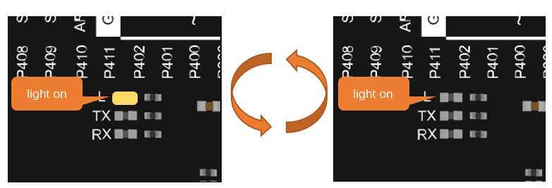
We have previously tried to make the LED marked with “L” blink on the control board. Now let us use electronic components and codes to reproduce the phenomenon, and try to understand their principle.

Project Control LED with Control Board

Now, try using control board to make LED blink through programing.

Component List

Components are basically the same with those in last section. Push button switch is no more needed.

Circuit Knowledge

Analog signal and Digital signal

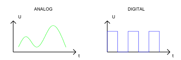
An Analog Signal is a continuous signal in both time and value. On the contrary, a Digital Signal or discrete-time signal is a time series consisting of a sequence of quantities. Most signals in life are analog signals. A familiar example of an Analog Signal would be how the temperature throughout the day is continuously changing and could not suddenly change instantaneously from 0℃ to 10℃.

However, Digital Signals can instantaneously change in value. This change is expressed in numbers as 1 and 0 (the basis of binary code). Their differences can more easily be seen when compared when graphed as below.

../../../_images/Chapter01_22.png

In practical applications, we often use binary as the digital signal, that is a series of 0’s and 1’s. Since a binary signal only has two values (0 or 1) it has great stability and reliability. Lastly, both analog and digital signals can be converted into the other.

Low level and high level

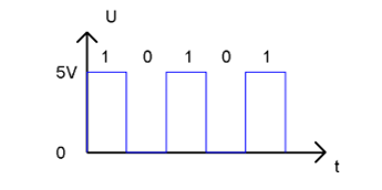
In a circuit, the form of binary (0 and 1) is presented as low level and high level.

Low level is generally equal to ground voltage(0V). High level is generally equal to the operating voltage of components.

The low level of the control board is 0V and high level is 5V, as shown below. When IO port on control board outputs high level, components of small power can be directly lit, like LED.

../../../_images/Chapter01_23.png

Code Knowledge

Before start writing code, we should learn about the basic programming knowledge.

Comments

Comments are the words used to explain for the sketches, and they won’t affect the running of code.

There are two ways to use comments of sketches.

  1. Symbol “//”

Contents behind “//” comment out the code in a single line.

1// this is a comment area in this line.

The content in front of “//” will not be affected.

1delay(1000);              // wait for a second
  1. Symbol “/”and “/”

Code can also be commented out by the contents starting with a “/” and finishing with a “/” and you can place it anywhere in your code, on the same line or several lines.

1/* this is comment area. */

Or

1/*
2    this is a comment line.
3    this is a comment line.
4*/

Data type

When programming, we often use digital, characters and other data. C language has several basic data types as follows:

int: A number that does not have a fractional part, an integer, such as 0, 12, -1;

float: A number that has a fractional part, such as 0.1, -1.2;

char: It means character, such as ‘a’, ‘@’, ‘0’;

For more about date types, please visit the website: https://www.Arduino.cc-Resources-Reference-Data Types.

Constant

A constant is a kind of data that cannot be changed, such as int type 0, 1, float type 0.1, -0.1, char type ‘a’, ‘B’.

Variable

A variable is a kind of data that can be changed. It consists of a name, a value, and a type. Variables need to be defined before using, such as:

1int i;

“int” indicates the type, “;” indicates the end of the statement. The statement is usually written in one single line; and these statements form the code.

After declaration of the variable, you can use it. The following is an assignment to a variable:

1i = 0;                    // after the execution, the value of i is 0

“=” is used to pass the value of a variable or constant on the right side to the variable on the left.

A certain number of variables can be declared in one statement, and a variable can be assigned multiple times. Also, the value of a variable can be passed to other variables. For example:

1int i, j;
2i = 0;                    // after the execution, the value of i is 0
3i = 1;                    // after the execution, the value of i is 1
4j = i;                    // after the execution, the value of j is 1

Function

A function is a collection of statements with a sequence of order, which performs a defined task. Let’s define a function void blink() as follows:

1void blink() {
2    digitalWrite(13, HIGH);
3    delay(1000);
4    digitalWrite(13, LOW);
5    delay(1000);
6}

“void” indicates that the function does not return a value (Chapter 4 will detail the return value of functions);

“()” its inside is parameters of a function (Chapter 2 will detail the parameters of the functions). No content inside it indicates that this function has no parameters;

“{}” contains the entire code of the function.

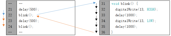
After the function is defined, it is necessary to be called before it is executed. Let’s call the function void blink(), as shown below.

1blink();

When the code is executed to a statement calling the function, the function will be executed. After execution of the function is finished, it will go back to the statement and execute the next statement.

../../../_images/Chapter01_24.png

Some functions have one or more parameters. When you call such functions, you need to write parameters inside “()”:

1digitalWrite(13, HIGH);   // turn the LED on (HIGH is the voltage level)
2delay(1000);              // wait for a second

Sketch

Sketch Control_LED_by_Control_Board

In order to make the LED blink, we need to make pin 13 of the control board output high and low level alternately.

We highly recommend you type the code manually instead of copying and pasting, so that you can develop your coding skills and get more knowledge.

 1/**********************************************************************
 2  Filename    : Sketch_1.2.1_Control_LED_by_Control_Board
 3  Description : Control LED by Control Board
 4  Auther      : www.freenove.com
 5  Modification: 2024/08/05
 6**********************************************************************/
 7
 8// the setup function runs once when you press reset or power the board
 9void setup() {
10  // initialize digital pin 13 as an output
11  pinMode(13, OUTPUT);
12}
13
14// the loop function runs over and over again forever
15void loop() {
16  digitalWrite(13, HIGH);   // turn the LED on (HIGH is the voltage level)
17  delay(1000);              // wait for a second
18  digitalWrite(13, LOW);    // turn the LED off by making the voltage LOW
19  delay(1000);              // wait for a second
20}

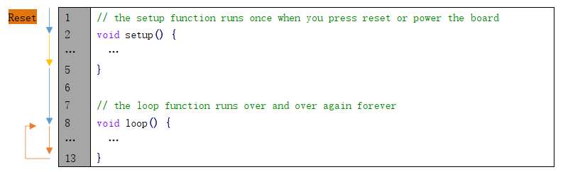
The code usually contains two basic functions: void setup() and void loop().

After control board is reset , the setup() function will be executed first, and then the loop() function will be executed.

setup() function is generally used to write code to initialize the hardware. And loop() function is used to write code to achieve certain functions. loop() function is executed repeatedly. When the execution reaches the end of loop(), it will jump to the beginning of loop() to run again.

Reset()

Reset operation will lead the code to be executed from the beginning. Switching on the power, finishing uploading the code and pressing the reset button will trigger reset operation.

../../../_images/Chapter01_27.png

In the setup () function, first, we set pin 13 of the control board as output mode, which can make the port output high level or low level.

1// initialize digital pin 13 as an output
2pinMode(13, OUTPUT);

Then, in the loop () function, set pin 13 of the control board to output high level to make LED light up.

1digitalWrite(13, HIGH);   // turn the LED on (HIGH is the voltage level)

Wait for 1000ms, which is 1s. delay() function is used to make control board wait for a moment before executing the next statement. The parameter indicates the number of milliseconds to wait for.

1delay(1000);              // wait for a second

Then set the 13 pint to output low level, and LED light off. One second later, the execution of loop () function will be completed.

1digitalWrite(13, LOW);    // turn the LED off by making the voltage LOW
2delay(1000);              // wait for a second

The loop() function is constantly being executed, so LED will keep blinking.

The functions called above are standard functions of the Arduino IDE, which have been defined in the Arduino IDE, and they can be called directly. We will introduce more common standard functions in later chapters.

For more standard functions and the specific use method, please visit https://www.arduino.cc-Resources-Reference-Functions.

Verify and upload the code, then the LED starts blinking.

../../../_images/Chapter01_33.png