Chapter Motor
Earlier, we have done a series of interesting projects with control board and basic electronic components. Now, let us study some movable electronic modules. In this chapter, we will learn to control a motor.
Project Control Motor with L293D
Now, we will use dedicated chip L293D to control the motor.
Component List
Control board x1
|
|||
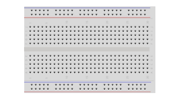
Breadboard x1
|
GPIO Extension Board x1
|
||
USB cable x1
|
Jumper M/M x10 Jumper F/M x2
|
||
Motor x1
|
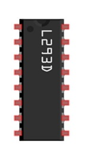
L293D x1
|
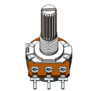
Rotary potentiometer x1 |
|


Component Knowledge
L293D
L293D is an IC chip (Integrated Circuit Chip) with a 4-channel motor drive. You can drive a unidirectional DC motor with 4 ports or a bi-directional DC motor with 2 ports or a stepper motor (stepper motors are covered later in this Tutorial).
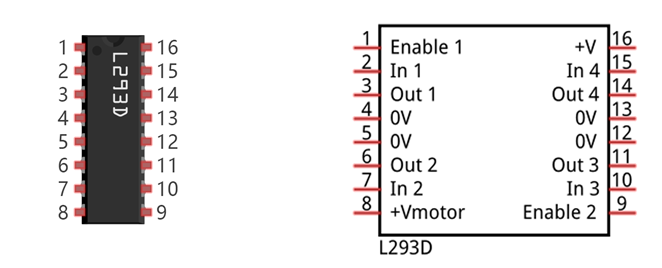
Port description of L293D module is as follows:
Pin name |
Pin number |
Description |
|---|---|---|
In x |
2, 7, 10, 15 |
Channel x digital signal input pin |
Out x |
3, 6, 11, 14 |
Channel x output pin, input high or low level according to In x pin, get connected to +Vmotor or 0V |
Enable1 |
1 |
Channel 1 and channel 2 enable pin, high level enable |
Enable2 |
9 |
Channel 3 and channel 4 enable pin, high level enable |
0V |
4, 5, 12, 13 |
Power cathode (GND) |
+V |
16 |
Positive electrode (VCC) of power supply, supply voltage 4.5~36V |
+Vmotor |
8 |
Positive electrode of load power supply, provide power supply for the Out pin x, the supply voltage is +V~36V |
For more details, please see datasheet.
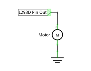
When using L293D to drive DC motor, there are usually two kinds of connection.
The following connection option uses one channel of the L239D, which can control motor speed through the PWM, However the motor then can only rotate in one direction.
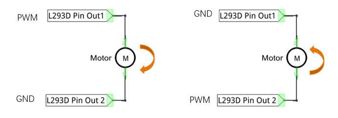
The following connection uses two channels of the L239D: one channel outputs the PWM wave, and the
other channel connects to GND, therefore you can control the speed of the motor. When these two channel
signals are exchanged, not only controls the speed of motor, but also can control the steering of the motor.
In practical use the motor is usually connected to channel 1 and by outputting different levels to in1 and in2 to control the rotational direction of the motor, and output to the PWM wave to Enable1 port to control the motor’s rotational speed. If the motor is connected to channel 3 and 4 by outputting different levels to in3 and in4 to control the motor’s rotation direction, and output to the PWM wave to Enable2 pin to control the motor’s rotational speed.
Circuit
Use pin A0 of the control board to detect the voltage of rotary potentiometer; pin 9 and pin 10 to control the motor’s rotation direction and pin 11 to output PWM wave to control motor speed.
Schematic diagram |
|
Hardware connection If you need any support, please feel free to contact us via: support@freenove.com |
|
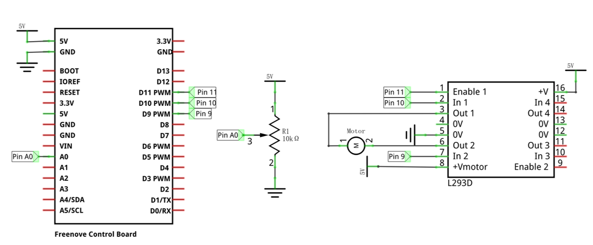
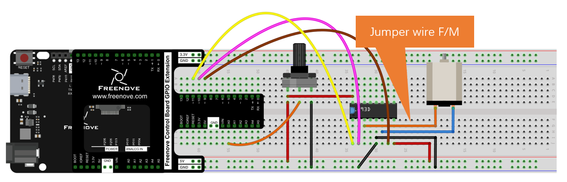
The DC electric power here can also be powered using 5V or 3.3V on the control board.
Sketch
Sketch Control_Motor_by_L293D
Now, write the code to control speed and rotation direction of motor through rotary potentiometer. When the potentiometer stays in the middle position, motor speed will be minimum, and when deviates intermediate position, the speed will increase. Also, if the potentiometer deviates from the middle position of potentiometer clockwise or counterclockwise, the rotation direction of the motor is different.
 1/**********************************************************************
 2  Filename    : Sketch_13.2.1_Control_Motor_by_L293D
 3  Description : Control Motor by L293D
 4  Auther      : www.freenove.com
 5  Modification: 2024/08/05
 6**********************************************************************/
 7
 8int in1Pin = 10;      // Define L293D channel 1 pin
 9int in2Pin = 9;       // Define L293D channel 2 pin
10int enable1Pin = 11;  // Define L293D enable 1 pin
11
12boolean rotationDir;  // Define a variable to save the motor's rotation direction, true and false are represented by positive rotation and reverse rotation.
13int rotationSpeed;    // Define a variable to save the motor rotation speed
14
15void setup() {
16  // Initialize the pin into an output mode:
17  pinMode(in1Pin, OUTPUT);
18  pinMode(in2Pin, OUTPUT);
19  pinMode(enable1Pin, OUTPUT);
20}
21
22void loop() {
23  int potenVal = analogRead(A0);  // Convert the voltage of rotary potentiometer into digital
24  // Compare the number with value 512, if more than 512, clockwise rotates, otherwise, counter clockwise rotates
25  rotationSpeed = potenVal - 512;
26  if (potenVal > 512)
27    rotationDir = true;
28  else
29    rotationDir = false;
30  // Calculate the motor speed, the far number of deviation from the middle value 512, the faster the control speed will be
31  rotationSpeed = abs(potenVal - 512);
32  // Control the steering and speed of the motor
33  driveMotor(rotationDir, map(rotationSpeed, 0, 512, 0, 255));
34}
35
36void driveMotor(boolean dir, int spd) {
37  // Control motor rotation direction
38  if (dir) {
39    digitalWrite(in1Pin, HIGH);
40    digitalWrite(in2Pin, LOW);
41  }
42  else {
43    digitalWrite(in1Pin, LOW);
44    digitalWrite(in2Pin, HIGH);
45  }
46  // Control motor rotation speed
47  analogWrite(enable1Pin, constrain(spd, 0, 255));
48}
In the code, we write a function to control the motor, and control the speed and steering through two parameters.
 1void driveMotor(boolean dir, int spd) {
 2  // Control motor rotation direction
 3  if (dir) {
 4    digitalWrite(in1Pin, HIGH);
 5    digitalWrite(in2Pin, LOW);
 6  }
 7  else {
 8    digitalWrite(in1Pin, LOW);
 9    digitalWrite(in2Pin, HIGH);
10  }
11  // Control motor rotation speed
12  analogWrite(enable1Pin, constrain(spd, 0, 255));
13}
In the loop () function, detect the digital value of rotary potentiometer, and convert it into the motor speed and steering through calculation.
 1void loop() {
 2  int potenVal = analogRead(A0);  // Convert the voltage of rotary potentiometer into digital
 3  // Compare the number with value 512, if more than 512, clockwise rotates, otherwise, counter clockwise rotates
 4  rotationSpeed = potenVal - 512;
 5  if (potenVal > 512)
 6    rotationDir = true;
 7  else
 8    rotationDir = false;
 9  // Calculate the motor speed, the far number of deviation from the middle value 512, the faster the control speed will be
10  rotationSpeed = abs(potenVal - 512);
11  // Control the steering and speed of the motor
12  driveMotor(rotationDir, map(rotationSpeed, 0, 512, 0, 255));
13}
- abs(x)
Computes the absolute value of a number.
Verify and upload the code, turn the shaft of rotary potentiometer, and then you can see the change of the motor speed and direction.