Chapter 16 74HC595 & Bar Graph LED
We have used LED Bar Graph to make a flowing water light, in which 10 GPIO ports of RPi are occupied. More GPIO ports mean that more peripherals can be connected to RPi, so GPIO resource is very precious. Can we make flowing water light with less GPIO ports? In this chapter, we will learn a component, 74HC595, which can achieve the target.
Project 16.1 Flowing Water Light
Now let us learn how to use the 74HC595 IC Chip to make a flowing water light using less GPIO.
Component knowledge
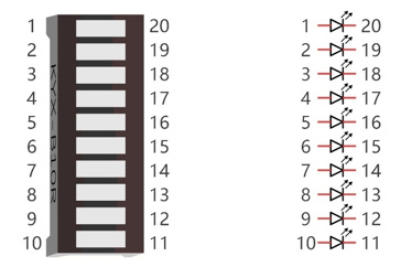
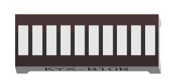
Bar Graph LED
A Bar Graph LED has 10 LEDs integrated into one compact component. The two rows of pins at its bottom are paired to identify each LED like the single LED used earlier.
74HC595
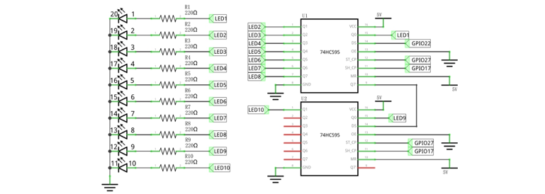
A 74HC595 chip is used to convert serial data into parallel data. A 74HC595 chip can convert the serial data of one byte into 8 bits, and send its corresponding level to each of the 8 ports correspondingly. With this characteristic, the 74HC595 chip can be used to expand the IO ports of a Raspberry Pi. At least 3 ports on the RPI board are required to control the 8 ports of the 74HC595 chip.
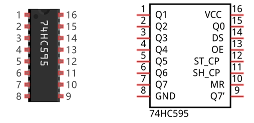
The ports of the 74HC595 chip are described as follows:
Pin name |
Pin number |
Description |
|---|---|---|
Q0-Q7 |
15, 1-7 |
Parallel Data Output |
VCC |
16 |
The Positive Electrode of the Power Supply, the Voltage is 2~6V |
GND |
8 |
The Negative Electrode of Power Supply |
DS |
14 |
Serial Data Input |
OE |
13 |
Enable Output, When this pin is in high level, Q0-Q7 is in high resistance state When this pin is in low level, Q0-Q7 is in output mode |
ST_CP |
12 |
Parallel Update Output: when its electrical level is rising, it will update the parallel data output. |
SH_CP |
11 |
Serial Shift Clock: when its electrical level is rising, serial data input register will do a shift. |
MR |
10 |
Remove Shift Register: When this pin is in low level, the content in shift register will be cleared. |
Q7’ |
9 |
Serial Data Output: it can be connected to more 74HC595 chips in series. |
For more details, please refer to the datasheet on the 74HC595 chip.
Component List
Freenove Projects Board for Raspberry Pi |
|
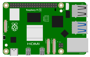
Raspberry Pi |
GPIO Ribbon Cable |
Bar Graph LED |
|
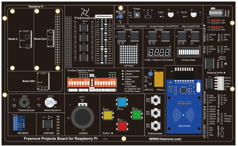
Circuit
Schematic diagram |
|
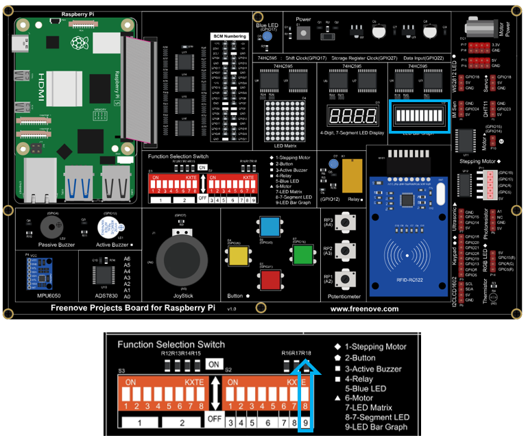
Hardware connection: |
|
Hint
If it dosen’t work, rotate the LED bar graph for 180°.
Note
If you have any concerns, please send an email to: support@freenove.com
Code
In this project we will make a flowing water light with a 74HC595 chip to learn about its functions.
C Code LightWater02
First, observe the project result, and then learn about the code in detail.
If you have any concerns, please send an email to: support@freenove.com
Use cd command to enter 16_FlowingLight02 directory of C code.
$ cd ~/Freenove_Kit/Code/C_Code/16_FlowingLight02
Use following command to compile “FlowingLight02.c” and generate executable file “FlowingLight02”.
$ gcc FlowingLight02.c -o FlowingLight02 -lwiringPi
Then run the generated file “FlowingLight02”.
$ ./FlowingLight02
After the program runs, you will see that Bar Graph LED starts with the flowing water pattern flashing from right to left and then back from left to right.
The following is the program code:
 1/**********************************************************************
 2* Filename    : FlowingLight02.c
 3* Description : Control LED by 74HC595
 4* Author      : www.freenove.com
 5* modification: 2024/07/29
 6**********************************************************************/
 7#include <wiringPi.h>
 8#include <stdio.h>
 9#include <wiringShift.h>
10
11#define dataPin  22   //DS Pin of 74HC595(Pin14)
12#define latchPin 27   //ST_CP Pin of 74HC595(Pin12)
13#define clockPin 17   //CH_CP Pin of 74HC595(Pin11)
14
15void _shiftOut(int dPin,int cPin,int order,int val){
16	int i;
17    for(i = 0; i < 10; i++){
18        digitalWrite(cPin,LOW);
19        if(order == LSBFIRST){
20            digitalWrite(dPin,((0x01&(val>>i)) == 0x01) ? HIGH : LOW);
21            delayMicroseconds(10);
22		}
23        else {
24            digitalWrite(dPin,((0x80&(val<<i)) == 0x80) ? HIGH : LOW);
25            delayMicroseconds(10);
26		}
27        digitalWrite(cPin,HIGH);
28        delayMicroseconds(10);
29	}
30}
31
32int main(void)
33{
34	int i;
35	unsigned long x;
36
37	printf("Program is starting ...\n");
38
39	wiringPiSetupGpio();//Initialize wiringPi. Use BCM Number.
40
41	pinMode(dataPin,OUTPUT);
42	pinMode(latchPin,OUTPUT);
43	pinMode(clockPin,OUTPUT);
44	while(1){
45		x=0x0001;
46		for(i=0;i<10;i++){
47			digitalWrite(latchPin,LOW);		// Output low level to latchPin
48			_shiftOut(dataPin,clockPin,LSBFIRST,x);// Send serial data to 74HC595
49			digitalWrite(latchPin,HIGH);   //Output high level to latchPin, and 74HC595 will update the data to the parallel output port.
50			x<<=1;      //make the variable move one bit to left once, then the bright LED move one step to the left once.
51			delay(100);
52		}
53		x=0x0200;
54		for(i=0;i<10;i++){
55			digitalWrite(latchPin,LOW);
56			_shiftOut(dataPin,clockPin,LSBFIRST,x);
57			digitalWrite(latchPin,HIGH);
58			x>>=1;
59			delay(100);
60		}
61	}
62	return 0;
63}
64
In the code, we configure three pins to control the 74HC595 chip and define a one-byte variable to control the state of the 10 LEDs (in the Bar Graph LED Module) through the 10 bits of the variable. The LEDs light ON when the corresponding bit is 1. If the variable is assigned to 0x01, that is 00000001 in binary, there will be only one LED ON.
1x=0x0001;
In the “while” loop of main function, use two loops to send x to 74HC595 output pin to control the LED. In one cycle, x will shift one bit to the LEFT in one cycle, then when data of x is sent to 74HC595, the LED that is turned ON will move one bit to the LEFT once.
1for(i=0;i<10;i++){
2	digitalWrite(latchPin,LOW);		// Output low level to latchPin
3	_shiftOut(dataPin,clockPin,LSBFIRST,x);// Send serial data to 74HC595
4	digitalWrite(latchPin,HIGH);   //Output high level to latchPin, and 74HC595 will update the data to the parallel output port.
5	x<<=1;      //make the variable move one bit to left once, then the bright LED move one step to the left once.
6	delay(100);
7}
In second cycle, the situation is the same. The difference is that x is shift from 0x80 to the RIGHT in order.
- << operator
“<<” is the left shift operator, which can make all bits of 1 byte shift by several bits to the left (high) direction and add 0 on the right (low). For example, shift binary 00000001 by 1 bit to left:
byte x = 1 << 1;

The result of x is 2(binary 00000010).

There is another similar operator” >>”. For example, shift binary 00000001 by 1 bit to right:
byte x = 1 >> 1;

The result of x is 0(00000000).

X <<= 1 is equivalent to x = x << 1 and x >>= 1 is equivalent to x = x >> 1
About shift function
-
void _shiftOut(uint8_t dPin, uint8_t cPin, uint8_t order, uint8_t val);
This is used to shift a 10-bit data value out with the data being sent out on dPin and the clock being sent out on the cPin. order is as above. Data is clocked out on the rising or falling edge - ie. dPin is set, then cPin is taken high then low - repeated for the 10 bits.
Python Code LightWater02
First, observe the project result, and then learn about the code in detail.
If you have any concerns, please send an email to: support@freenove.com
Use cd command to enter 16_FlowingLight02 directory of Python code.
$ cd ~/Freenove_Kit/Code/Python_GPIOZero_Code/16_FlowingLight02
Use python command to execute Python code “FlowingLight02.py”.
$ python FlowingLight02.py
After the program runs, you will see that Bar Graph LED starts with the flowing water pattern flashing from right to left and then back from left to right.
The following is the program code:
 1#!/usr/bin/env python3
 2#############################################################################
 3# Filename    : LightWater02.py
 4# Description : Control LED with 74HC595
 5# Author      : www.freenove.com
 6# modification: 2024/07/29
 7########################################################################
 8from gpiozero import OutputDevice
 9import time
10# Defines the data bit that is transmitted preferentially in the shiftOut function.
11LSBFIRST = 1
12MSBFIRST = 2
13# define the pins for 74HC595
14dataPin   = OutputDevice(22)      # DS Pin of 74HC595(Pin14)
15latchPin  = OutputDevice(27)      # ST_CP Pin of 74HC595(Pin12)
16clockPin  = OutputDevice(17)      # CH_CP Pin of 74HC595(Pin11)
17
18# shiftOut function, use bit serial transmission.
19def shiftOut(order,val):
20    for i in range(0,8):
21        clockPin.off()
22        if(order == LSBFIRST):
23            dataPin.on() if (0x01&(val>>i)==0x01) else dataPin.off()
24        elif(order == MSBFIRST):
25            dataPin.on() if (0x80&(val<<i)==0x80) else dataPin.off()
26        clockPin.on()
27
28def showLedbar(order,val):
29    val1 = val >> 8 & 0xff
30    val2 = val & 0xff
31    shiftOut(order, val1)
32    shiftOut(order, val2)
33
34def loop():
35    while True:
36        x=0x001
37        for i in range(0,10):
38            latchPin.off()# Output low level to latchPin
39            showLedbar(MSBFIRST,x) # Send serial data to 74HC595
40            latchPin.on()   # Output high level to latchPin, and 74HC595 will update the data to the parallel output port.
41            x<<=1 # make the variable move one bit to left once, then the bright LED move one step to the left once.
42            time.sleep(0.1)
43        x=0x200
44        for i in range(0,10):
45            latchPin.off()
46            showLedbar(MSBFIRST,x)
47            latchPin.on()
48            x>>=1
49            time.sleep(0.1)
50
51def destroy():
52    latchPin.off()
53    shiftOut(MSBFIRST, 0x00)
54    shiftOut(MSBFIRST, 0x00)
55    latchPin.on()
56    dataPin.close()
57    latchPin.close()
58    clockPin.close()
59
60if __name__ == '__main__': # Program entrance
61    print ('Program is starting...' )
62    try:
63        loop()
64    except KeyboardInterrupt:  # Press ctrl-c to end the program.
65        print("Ending program")
66    finally:
67        destroy()
In the code, we define a shiftOut() function, which is used to output values with bits in order, where the dPin for the data pin, cPin for the clock and order for the priority bit flag (high or low). This function conforms to the operational modes of the 74HC595. LSBFIRST and MSBFIRST are two different flow directions.
1def shiftOut(order,val):
2    for i in range(0,8):
3        clockPin.off()
4        if(order == LSBFIRST):
5            dataPin.on() if (0x01&(val>>i)==0x01) else dataPin.off()
6        elif(order == MSBFIRST):
7            dataPin.on() if (0x80&(val<<i)==0x80) else dataPin.off()
8        clockPin.on()
In the loop() function, we use two loops to achieve the action goal. First, define a variable x=0x0001. When it is transferred to the output port of 74HC595, the low bit outputs high level, then an LED turns ON. Next, x is shifted one bit, when x is transferred to the output port of 74HC595 once again, the LED that turns ON will be shifted. Repeat the operation, over and over and the effect of a flowing water light will be visible. If the direction of the shift operation for x is different, the flowing direction is different.
 1def loop():
 2    while True:
 3        x=0x001
 4        for i in range(0,10):
 5            latchPin.off()# Output low level to latchPin
 6            showLedbar(MSBFIRST,x) # Send serial data to 74HC595
 7            latchPin.on()   # Output high level to latchPin, and 74HC595 will update the data to the parallel output port.
 8            x<<=1 # make the variable move one bit to left once, then the bright LED move one step to the left once.
 9            time.sleep(0.1)
10        x=0x200
11        for i in range(0,10):
12            latchPin.off()
13            showLedbar(MSBFIRST,x)
14            latchPin.on()
15            x>>=1
16            time.sleep(0.1)